Coarse wavelength division multiplexing filter

A wavelength division multiplexing and filter technology, applied in the field of silicon-based photonic integrated chips, can solve problems such as insertion loss and device size increase, increase device size, reduce filter athermal characteristics, etc., to solve wiring difficulties, Effect of avoiding extra loss and phase deviation, size reduction

Active Publication Date: 2019-10-08
ZHONGXING PHOTONICS TECH CO LTD
View PDF5 Cites 5 Cited by
  • Summary
  • Abstract
  • Description
  • Claims
  • Application Information

AI Technical Summary

Problems solved by technology

In this kind of scheme, the first thing to face is the problem of polarization conversion. It is necessary to convert the polarization state of the input and output light, and a cascaded polarization splitter converter (Polarization Splitter Rotator, PSR) is required, which will bring about insertion loss and device size. increase
In addition, the thermo-optic coefficients of the Transverse Magnetic (TM) mode and the Transverse Electric (TE) mode only have a large difference in thick silicon, and in thin silicon, their thermo-optic coefficients have a small difference. Suitable for athermal design of filter
TE 1 mode is often chosen for an athermal design in thin silicon, but due to the TE 1 The characteristics of the mode itself, it still needs waveguide and mode conversion in the trace to complete the athermal design, which increases the size of the device and reduces the athermal characteristics of the filter

Method used


Image

  • Coarse wavelength division multiplexing filter
  • Coarse wavelength division multiplexing filter
  • Coarse wavelength division multiplexing filter

Examples


Embodiment Construction

[0032] In order to make the purpose, technical solution and advantages of the present invention more clear, the embodiments of the present invention will be described in detail below in conjunction with the accompanying drawings. It should be noted that, in the case of no conflict, the embodiments in the present application and the features in the embodiments can be combined arbitrarily with each other.

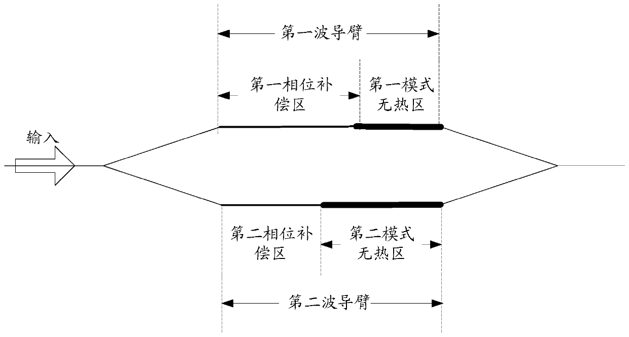
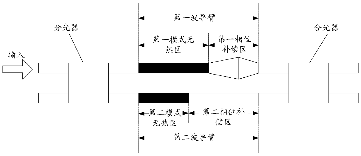
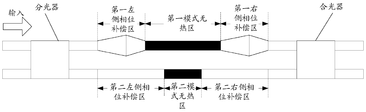
[0033] In an ordinary athermal filter, since the athermal design will make the waveguide lengths of the two arms of the MZI different, it is inevitable to use Bend for phase and length compensation for the waveguide wiring. However, Bend itself will produce a large phase error in actual processing. In addition, for TE 1 Mode, the loss of Bend is strong; it needs to be converted into the mode before entering the Bend, otherwise a curved waveguide with a large radius will be required. However, the size of the filter will be significantly increased after mode conversion, and a ...


PUM


Abstract

The invention discloses a coarse wavelength division multiplexing filter which comprises a first waveguide arm for transmitting a first mode of light waves and a second waveguide arm for transmittinga second mode of light waves. The first and second waveguide arms form an MZI type filter structure, the first waveguide arm comprise a first phase compensation area and a first mode heat-free area, and the second waveguide arm comprises a second phase compensation area and a second mode heat-free area; the lengths of the first and second heat-free areas satisfy preset heat-free requirements; andthe first and second compensation areas keep the relative phase shaft between the first and second waveguide arms unchanged, and compensate length difference between the first and second heat-free areas. Each of the two waveguide arms is provided with the mode heat-free area and the phase compensation area, so that a heat-free filter structure with equal length of two arms is realized, use of a bending waveguide or negative refractive index material is not needed, and waveguide or mode switching is not needed.

Description

technical field [0001] The present application relates to but not limited to the technical field of silicon-based photonic integrated chips, and in particular relates to a Coarse Wavelength Division Multiplexing (CWDM) filter. Background technique [0002] As a wave division and multiplexing device, a filter has an important application in a wavelength division multiplexing (Wavelength Division Multiplexing, WDM) communication system. The development of off-chip filters is relatively mature, but silicon photonics-based filters are still in the stage of exploration and development. At present, the main technical paths of silicon-based filters are: microring resonator, arrayed waveguide grating (ArrayedWaveguide Grating, AWG), cascaded Mach Zehnder Interferometer (MZI) and concave grating, etc. Realize the requirements of the communication system for the flat-top effect of the filter passband. However, silicon material has a large thermo-optic coefficient, and the refractive...

Claims


Application Information

Patent Timeline
Patent Type & Authority Applications(China)
IPC IPC(8): G02B5/20
CPCG02B5/20
Inventor 刘万元沈百林邵永波李蒙
Owner ZHONGXING PHOTONICS TECH CO LTD
Why Eureka
Try Eureka