A dimmable led light circuit

A technology of LED lamp circuit and light-emitting circuit, which is applied in the direction of light source, electric light source, electrical components, etc., and can solve the problems of high power consumption and failure to achieve the best use effect

Active Publication Date: 2021-04-20
YINGTAN YANKON GRP CO LTD +2
View PDF6 Cites 0 Cited by
  • Summary
  • Abstract
  • Description
  • Claims
  • Application Information

AI Technical Summary

Problems solved by technology

With the popularization of intelligent dimming control technology, the dimming method of traditional dimming controllers can no longer meet the needs of users. The intelligent dimming controller has the functions of intelligent communication and remote control, and there are many dimming modes. , has replaced traditional dimming controllers in some applications
A general intelligent dimming controller usually has a live wire input terminal, a neutral line input terminal, a first output terminal and a second output terminal. The live wire input terminal of the intelligent dimming controller is connected to the mains live wire. The neutral line input terminal is connected to the mains neutral line. The existing dimmable LED lamp circuit has a dimming matching circuit and consumes a lot of power. When used together with an intelligent dimming controller, it cannot achieve the desired effect. best use

Method used


Image

  • A dimmable led light circuit
  • A dimmable led light circuit
  • A dimmable led light circuit

Examples


Embodiment 1

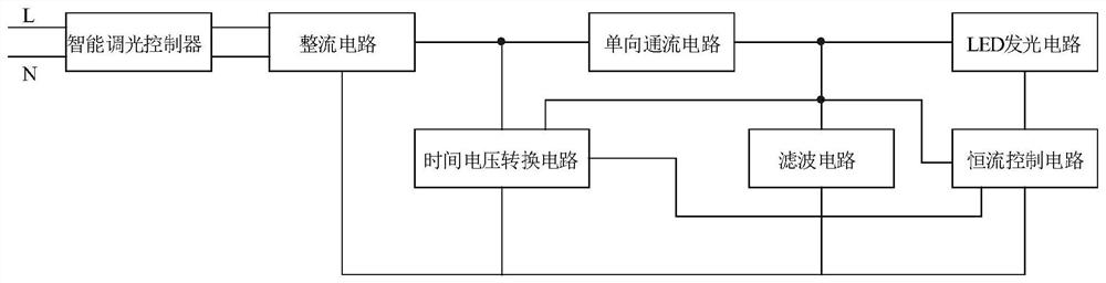
[0021] Embodiment one: if figure 2 As shown, a dimmable LED lamp circuit includes a rectifier circuit and an LED lighting circuit. The dimmable LED lamp circuit also includes a one-way current flow circuit, a filter circuit, a constant current control circuit and a time-to-voltage conversion circuit. The circuit is connected with an intelligent dimming controller, and the intelligent dimming controller outputs the AC voltage after chopper processing, including zero voltage at the zero voltage moment and non-zero voltage at the non-zero voltage moment; the filter circuit has a storage After the dimmable LED lamp circuit is connected to the mains through the intelligent dimming controller, the voltage at both ends of the filter circuit has been maintained at more than half of the peak value of the AC voltage of the mains. When the AC voltage of the mains is controlled by the intelligent dimming When the output voltage of the rectifier circuit is less than the voltage across the...

Embodiment 2

[0023] Embodiment 2: This embodiment is basically the same as Embodiment 1, the difference is:

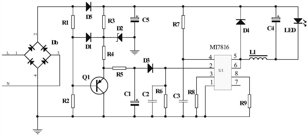
[0024] Such as image 3 As shown, in this embodiment, the time voltage conversion circuit includes a first resistor R1, a second resistor R2, a third resistor R3, a fourth resistor R4, a fifth resistor R5, a sixth resistor R6, a first capacitor C1, a second The capacitor C2, the first diode D1, the second diode D2, the third diode D3 and the first triode Q1, the first capacitor C1 is an electrolytic capacitor, and the second diode D2 is a Zener diode, The first transistor Q1 is a PNP transistor, the first diode D1 and the third diode D3 are rectifier diodes, one end of the first resistor R1 is the input end of the time-voltage conversion circuit, and the other end of the first resistor R1 , one end of the second resistor R2, the anode of the first diode D1 are connected to the base of the first triode Q1, one end of the third resistor R3 is the anode of the time-voltage conversion...


PUM


Abstract

The invention discloses a dimmable LED lamp circuit, which comprises a rectification circuit, an LED light-emitting circuit, a one-way flow circuit, a filter circuit, a constant current control circuit and a time-voltage conversion circuit, and the rectification circuit is connected with an intelligent dimming controller. In a change cycle of the mains voltage, even if the output terminal of the intelligent dimming controller remains in the on state, its output terminal has two output current states: the state where the output current is not zero and the state where the output current is zero. The intelligent dimming controller performs chopping control on the mains AC voltage at the low voltage moment when the output current is zero, and sends a control signal to the LED lamp circuit by controlling the chopping time; the advantage is that it can be compatible with the intelligent dimming controller, Composing an intelligent lighting system with an intelligent dimming controller is of great significance for improving the market competitiveness of dimmable LED lights and expanding their application prospects.

Description

technical field [0001] The invention relates to an LED lamp circuit, in particular to a dimmable LED lamp circuit. Background technique [0002] At present, the working principle of the dimmable LED lamp is to control the input power of the dimmable LED lamp by chopping the sine wave voltage at the input end to adjust the effective voltage at the input end, so that the dimmable LED lamp emits the corresponding input effective voltage brightness. The dimmable LED lamp includes a bracket and a dimmable LED lamp circuit installed on the bracket. The dimmable LED lamp circuit is the main part of the dimmable LED lamp. The performance of the dimmable LED lamp directly depends on the adjustable Light performance of the LED lamp circuit. [0003] The structural block diagram of the existing dimmable LED lamp circuit is as follows: figure 1 As shown, it mainly includes a rectifier circuit, a dimming matching circuit, a dimming control circuit, a flicker-removing circuit and an LE...

Claims


Application Information

Patent Timeline
Patent Type & Authority Patents(China)
IPC IPC(8): H05B45/10H05B45/345H05B45/32H05B44/00
CPCH05B45/00H05B45/10Y02B20/30Y02B20/40
Inventor 俞贤晓
Owner YINGTAN YANKON GRP CO LTD
Why Eureka
Try Eureka