Novel support-free shear wall concrete replacing device and novel support-free shear wall concrete replacing method
A shear wall, unsupported technology, used in building maintenance, construction, building construction, etc., can solve problems such as hidden structural hazards and increased shear wall stress, and achieve the effects of solving stress difference, simple installation and simple method.
- Summary
- Abstract
- Description
- Claims
- Application Information
AI Technical Summary
Problems solved by technology
Method used
Image

Examples
Embodiment 1
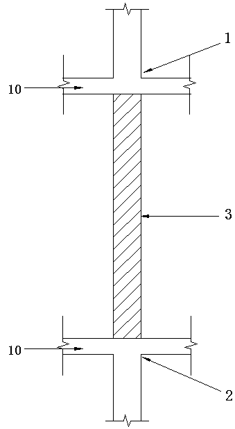
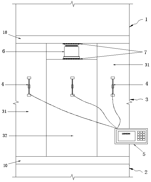
[0032] A new type of unsupported replacement shear wall concrete device, refer to the diagram and figure 2 , including superstructure 1, substructure 2 and replacement area 3 between superstructure 1 and lower upper shear force 2, said superstructure 1 and lower upper shear force 2 including beam or floor 1 at the junction with replacement area 3 The replacement area 3 includes the original wall 31 and the replacement wall 32, the replacement wall 32 is adjacent to the original wall 31; and the replacement wall 32 and the original wall 31 are provided with The vertical vibrating wire strain gauge 4, the top of the replacement wall 32 is also provided with a stress conversion jack 6. The vibrating wire strain gauge 4 is used to monitor the change of the stress of each section of the wall in different periods during the construction process, and the stress conversion jack 6 is used to apply pressure to the replacement wall 32 below it to make it bear the stress Reach the conve...
Embodiment 2
[0035] A novel unsupported method for replacing shear wall concrete, comprising steps as follows:
[0036] 1) Divide the shear wall in area 3 to be replaced into several sections to be demolished according to the measured strength of the original structural concrete and the load of the superstructure; Set up temporary supports.
[0037] 2) Install a vertical vibrating wire strain gauge 4 on the adjacent original wall 31 to be demolished, and the vibrating wire strain gauge 4 is connected to the strain tester 5 to record the strain of the original wall 31 Initial value I.
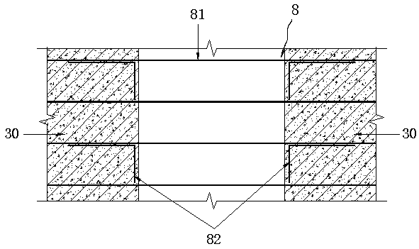
[0038] 3) Use the BOSH-11 machine to remove the original wall 31 to be demolished in the first section, and record the strain value II of the vibrating wire strain gauge 4 on the adjacent shear wall; minimize the disturbance to the adjacent parts when removing , and the steel structure 8 in the replacement area 3 should be avoided to be damaged during chiseling.
[0039] 4) After chiseling, clean up the r...
PUM
| Property | Measurement | Unit |
|---|---|---|
| Height | aaaaa | aaaaa |
Abstract
Description
Claims
Application Information
 - Generate Ideas
- Intellectual Property
- Life Sciences
- Materials
- Tech Scout
- Unparalleled Data Quality
- Higher Quality Content
- 60% Fewer Hallucinations
Browse by: Latest US Patents, China's latest patents, Technical Efficacy Thesaurus, Application Domain, Technology Topic, Popular Technical Reports.
© 2025 PatSnap. All rights reserved.Legal|Privacy policy|Modern Slavery Act Transparency Statement|Sitemap|About US| Contact US: help@patsnap.com