Check patentability & draft patents in minutes with Patsnap Eureka AI!

Novel electrode electro-optical Q switch

An electrode and electro-optic technology, applied in the field of lasers, can solve the problems of rising device costs and lengthening crystals

Inactive Publication Date: 2019-10-11
FUJIAN CASTECH CRYSTALS
View PDF0 Cites 0 Cited by
  • Summary
  • Abstract
  • Description
  • Claims
  • Application Information

AI Technical Summary

Problems solved by technology

However, most of the electrodes used in today's DKDP switches are ring-shaped electrodes on the side of the crystal. In order to consider the uniformity of the electric field, the length of the crystal must be appropriately lengthened when the aperture increases, resulting in an increase in the overall device cost.

Method used


Image

  • Novel electrode electro-optical Q switch
  • Novel electrode electro-optical Q switch

Examples


Embodiment Construction

[0011] Below in conjunction with accompanying drawing, the present invention will be further described,

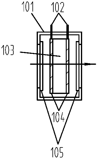
[0012] The overall device such as figure 1 As shown, 101 is a structural shell, 102 is a pin connecting the driving and transparent electrodes, 103 is a sheet electro-optic crystal, 104 is a transparent electrode, and 105 is a protective window fixed on the shell. The transparent electrode 104 is bonded to the light-transmitting surface of the sheet-shaped electro-optic crystal 103 through the side conductive glue, and the contact pin 102 is bonded to the side of the transparent electrode 103 through the conductive glue. The structural casing 101 is made of insulating material, and protective windows 105 are installed at both ends of the light transmission direction.

[0013] Since the longitudinal electro-optic effect of the crystal 103 is used, the light passing direction is consistent with the direction of the electric field, and the deflection of the refractive index ...


PUM


Abstract

The invention relates to the field of laser, in particular to a novel electrode electro-optical Q switch. According to the novel electrode electro-optical Q switch, a flaky electro-optical crystal isadopted; transparent electrodes are mounted in front of the two light-transmitting surfaces of the crystal by utilizing the longitudinal electro-optical effect of the crystal; and the deflection of alight beam polarization direction is realized by pressurizing the transparent electrodes. Due to the fact that the electrodes are directly mounted at the two ends of the light-transmitting surface ofthe crystal, the electric field uniformity is good, and the working voltage of the longitudinal electro-optical effect is independent of the crystal size, so that the shorter crystal with the larger caliber can be selected on the premise of ensuring no breakdown, and the cost is reduced. The electro-optical switch is simple in structure, large in light-transmitting caliber and capable of flexiblymeeting the use requirements. In addition, all the optical elements in the electro-optical Q switch can be glued into a whole through optical contact or optic bonding.

Description

technical field [0001] This patent relates to invention patents in the field of lasers, in particular to a new type of electrode electro-optical Q switch. Background technique [0002] Laser Q-switching technology, also called Q-switching technology, is a technology for obtaining high peak power and narrow pulse width laser pulses. [0003] The Q value is a quality factor used to describe the quality of the resonant circuit. If the Q value is low, the cavity loss is large, the device threshold is high, and it is not easy to form laser oscillation; the Q value is high, the cavity loss is small, the device threshold is low, and it is easy to form a laser. oscillation. The basic principle of Q-switching is to control the Q value of the resonant cavity by some method (that is, to control the loss of the resonant cavity). That is to try to increase the oscillation threshold of the device in the early stage of optical pumping, thereby suppressing the generation of laser oscillat...

Claims


Application Information

Patent Timeline
Patent Type & Authority Applications(China)
IPC IPC(8): H01S3/115
CPCH01S3/115
Inventor 吴季王城强郭杭涛刘红梅张星陈秋华陈伟
Owner FUJIAN CASTECH CRYSTALS
Features
  • R&D
  • Intellectual Property
  • Life Sciences
  • Materials
  • Tech Scout
  • Unparalleled Data Quality
  • Higher Quality Content
  • 60% Fewer Hallucinations
Learn More