
Electrostatic generator, method for increasing output power, charging method and wearable equipment

A charging method and generator technology, applied in the direction of induction generators, etc., can solve the problems of high equivalent charge density, low output power, high output power, etc., and achieve the effects of reduced charge density, high output power, and increased output power

Active Publication Date: 2019-10-11
TSINGHUA UNIV
View PDF7 Cites 3 Cited by
  • Summary
  • Abstract
  • Description
  • Claims
  • Application Information

AI Technical Summary

Problems solved by technology

For this reason, the present invention proposes an electrostatic generator, the available equivalent charge density of the electrostatic generator is high, the capacitance is small, and the output power is high, which can solve the problem of low output power when the electrostatic generator is used to provide electric energy

Method used


Image

  • Electrostatic generator, method for increasing output power, charging method and wearable equipment
  • Electrostatic generator, method for increasing output power, charging method and wearable equipment
  • Electrostatic generator, method for increasing output power, charging method and wearable equipment

Examples


Embodiment 1

[0102] Embodiment 1 will show a rotary electrostatic generator.

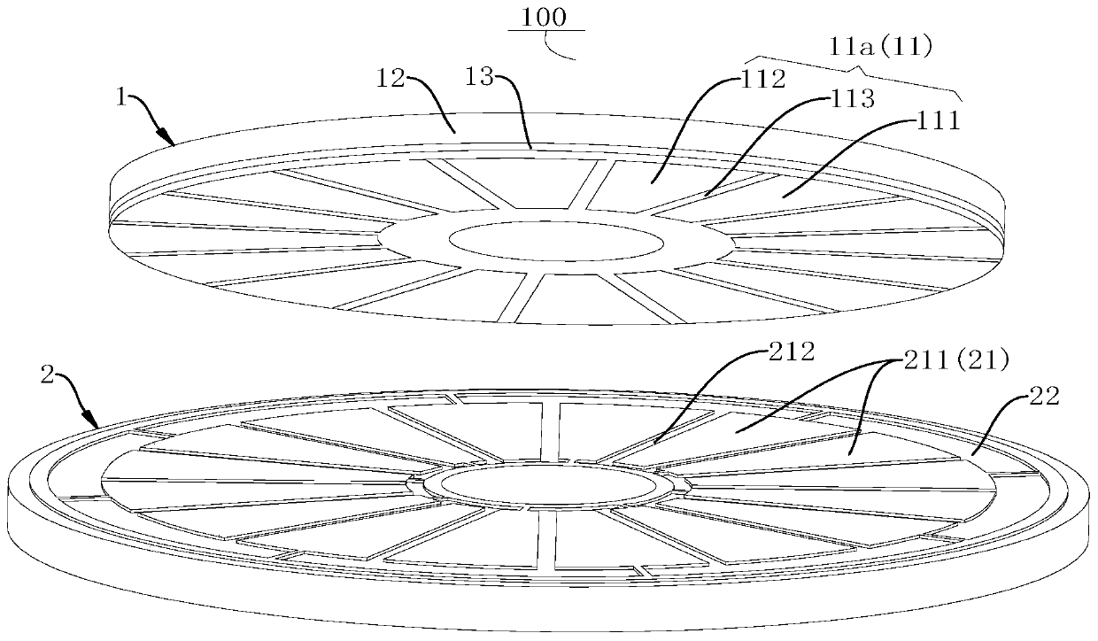
[0103] Such as figure 1 As shown, the rotary electrostatic generator includes a rotor 1 and a stator 2 that are generally circular. Wherein the rotor 1 comprises: an electret film 11a, a rotor base 12 and an adhesive layer 13, wherein the electret film 11a is bonded on the rotor base 12 through the adhesive layer 13, and the electret film 11a is made of PTFE, And the thickness of the electret film 11a is 0.001-0.3 mm, and the rotor base 12 is made of foaming material. The charging voltage of the electret film 11a ranges from ±300V to ±4500V. The adhesive layer 13 adopts PI double-sided adhesive tape. The electret film 11a includes a plurality of first charged electrets 111 and a plurality of second charged electrets 112 of the same shape, and a plurality of first charged electrets 111 and a plurality of second charged electrets The bodies 112 are alternately arranged in the circumferential direction of the p...

Embodiment 2

[0106] Embodiment 2 also shows a rotary electrostatic generator.

[0107] The difference is that if Figure 9 As shown, the electret film 11a in Embodiment 1 is replaced by an electret plate 11b, the thickness of the electret plate 11b is 0.5-3 mm, and the rotor base 12 is eliminated. The electret plate 11b is made of CYTOP material. The voltage required for charging the electret plate 11b is relatively high, and the charging voltage ranges from ±5000V to ±30000V. The stator base 22 is made of foamed polypropylene.

Embodiment 3

[0109] Embodiment 3 will show a patterned charging electrode 300 used for charging the electret film 11a of the rotary electrostatic generator in Embodiment 1 or the electret plate 11b in Embodiment 2.

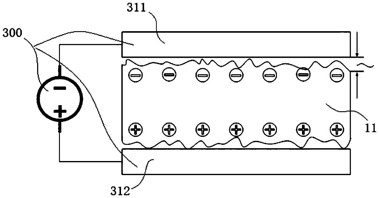
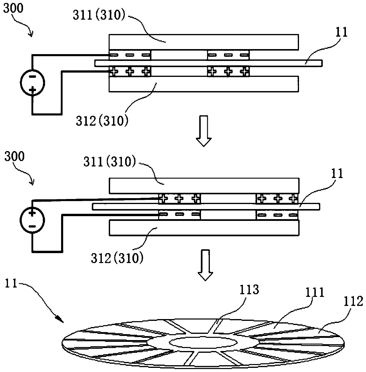
[0110] Such as Figure 4a and Figure 4b As shown, the patterned charging electrode 300 includes a first charging electrode 311 and a second charging electrode 312 oppositely arranged, and the first charging electrode 311 includes a first electrode plate 311a, a first electrode 311b and a first positioning piece 311c, correspondingly, The second charging electrode 312 includes a second electrode plate 312a, a second electrode 312b and a second positioning piece 312c. The first electrode 311b is circumferentially arranged on the surface of the first pole plate 311a, and the second electrode 312b is circumferentially arranged on the surface of the second electrode 312a, wherein the shape of the first electrode 311b, the shape of the second electrode 312b and the first The shap...


PUM


Abstract

The invention discloses an electrostatic generator, a method for increasing the output power, a charging method and wearable equipment, wherein the electrostatic generator comprises a rotor and a stator; the rotor comprises a positive and negative charge electret; the positive and negative charge electret comprises an electret body; a positive charge area and a negative charge area are formed on the electret body at intervals; a first charge electret and a second charge electret, which are respectively positioned in the two charge areas, are formed on the electret body; the stator comprises astator substrate and an electrode; the electrode is provided with the same number of corresponding electrode bodies corresponding to the first charge electret and the second charge electret; and the stator substrate is made by a foam material, the dielectric constant of which is 1-3. According to the electrostatic generator in the embodiment of the invention, the positive and negative charge electret of the rotor has positive charge and negative charge at the same time; the effective charge density is increased by one time; the dielectric constant of the foam material is relatively small; thenatural capacity of the electrode can be reduced; and, compared with the ordinary electrostatic generator, the output power is increased by 5-6 times.

Description

technical field [0001] The invention belongs to the technical field of electrostatic generators, in particular to an electrostatic generator, a method for increasing output power, a charging method and a wearable device. Background technique [0002] With the rapid development of science and technology, the Internet of Things and wearable devices have begun to enter our daily lives and become an indispensable part. In order to meet the energy supply requirements of the Internet of Things, sensor networks, portable and wearable electronic devices, etc., the development of micro generators with small size, light weight, low cost and continuous energy supply provides cheap, convenient, Long-lasting energy has become necessary. [0003] Renewable energy such as low-speed wind energy, wave and tidal energy, and the kinetic energy generated by people and various objects have a wide distribution range, and most of them have not been developed and utilized. How to convert them into...

Claims


Application Information

Patent Timeline
Patent Type & Authority Applications(China)
IPC IPC(8): H02N1/08
CPCH02N1/08
Inventor 叶雄英吴子博毕明朝
Owner TSINGHUA UNIV
Learn More