Small celestial body landing trajectory optimizing method considering gravitation attitude and orbit coupling effect

A coupling effect and small celestial body technology, applied in design optimization/simulation, space navigation equipment, special data processing applications, etc., can solve problems such as trajectory optimization algorithms that cannot be considered, damage to fuel consumption, and coupling effects increase

Active Publication Date: 2019-10-15
BEIJING UNIV OF POSTS & TELECOMM
View PDF5 Cites 7 Cited by
  • Summary
  • Abstract
  • Description
  • Claims
  • Application Information

AI Technical Summary

Problems solved by technology

When the distance between the detector and the celestial body is relatively long, the influence of gravity on the detector is not obvious, and the coupling effect is small and negligible; however, during the process of the detector landing on the small celestial body, the distance between the two gradually approaches, which will lead to the gradual coupling effect. increase
At the same time, the irregular gravitational field caused by the irregular shape of small celestial bodies will also intensify this eff

Method used


Image

  • Small celestial body landing trajectory optimizing method considering gravitation attitude and orbit coupling effect
  • Small celestial body landing trajectory optimizing method considering gravitation attitude and orbit coupling effect
  • Small celestial body landing trajectory optimizing method considering gravitation attitude and orbit coupling effect

Examples


Embodiment Construction

[0065] In order to better understand the technical solutions of the present invention, the embodiments of the present invention will be described in detail below in conjunction with the accompanying drawings.

[0066] It should be clear that the described embodiments are only some of the embodiments of the present invention, not all of them. Based on the embodiments of the present invention, all other embodiments obtained by persons of ordinary skill in the art without creative efforts all belong to the protection scope of the present invention.

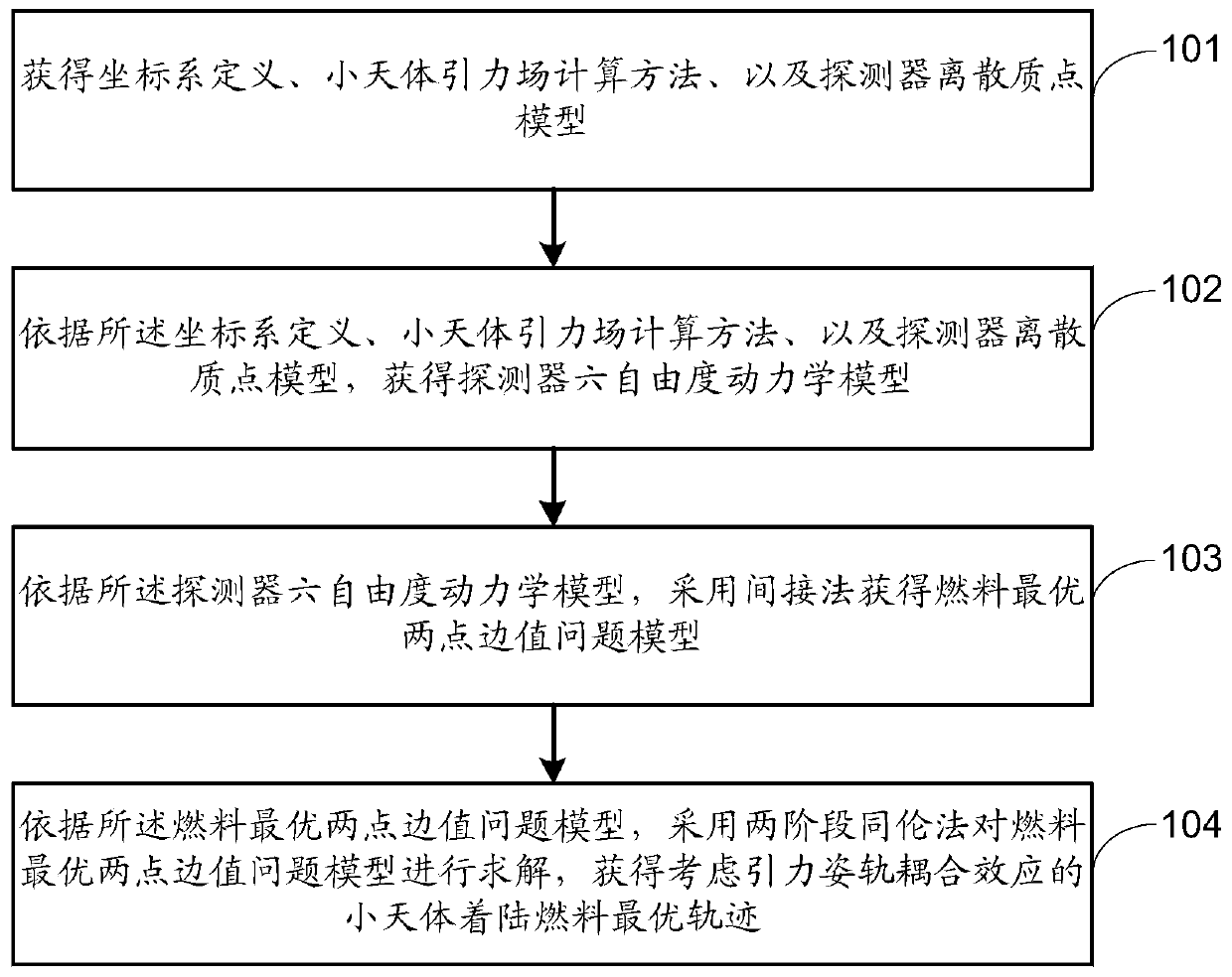
[0067] The embodiment of the present invention provides a method for optimizing the landing trajectory of a small celestial body considering the gravitational attitude-orbit coupling effect, and its flow chart is as follows figure 1 As shown, the method includes the following steps:

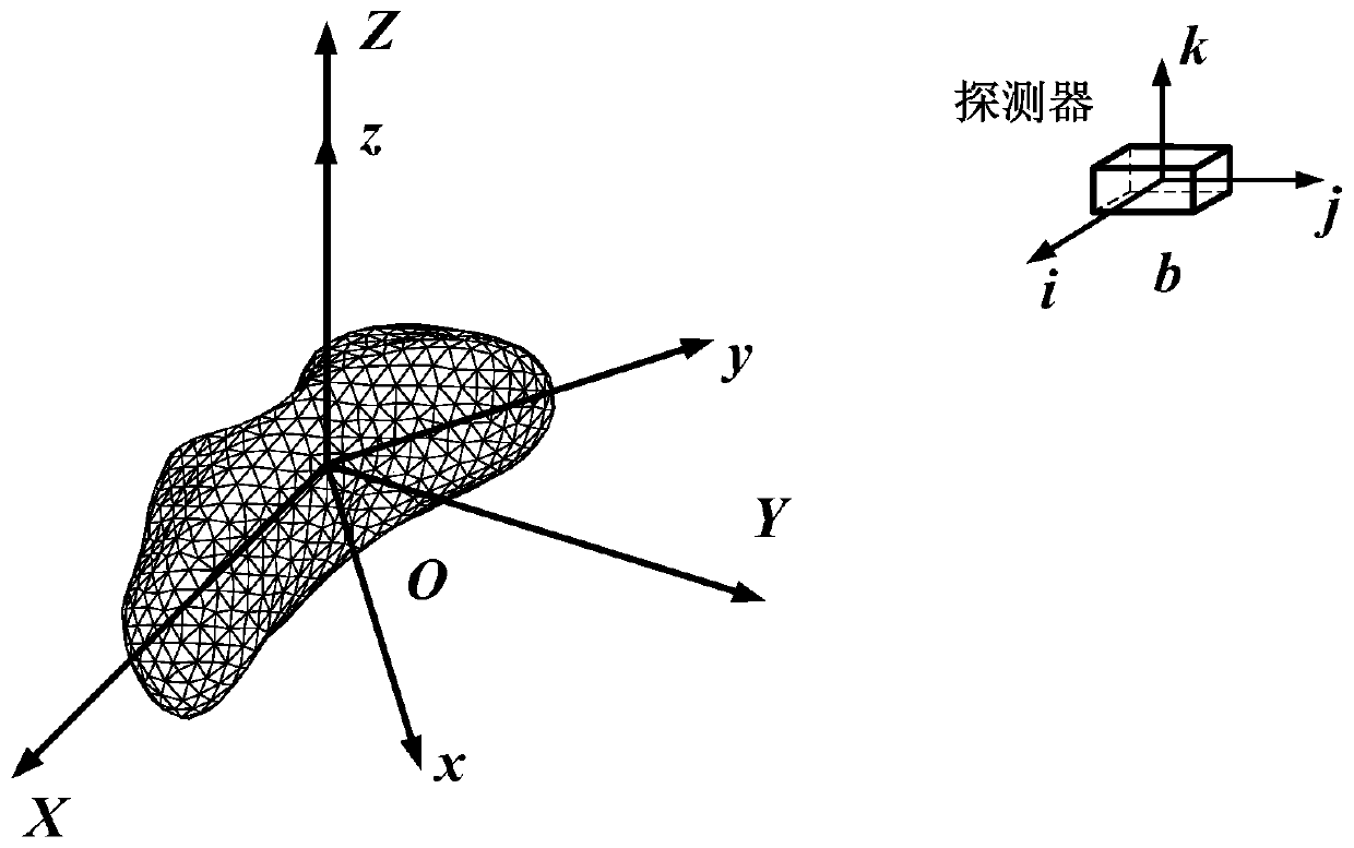
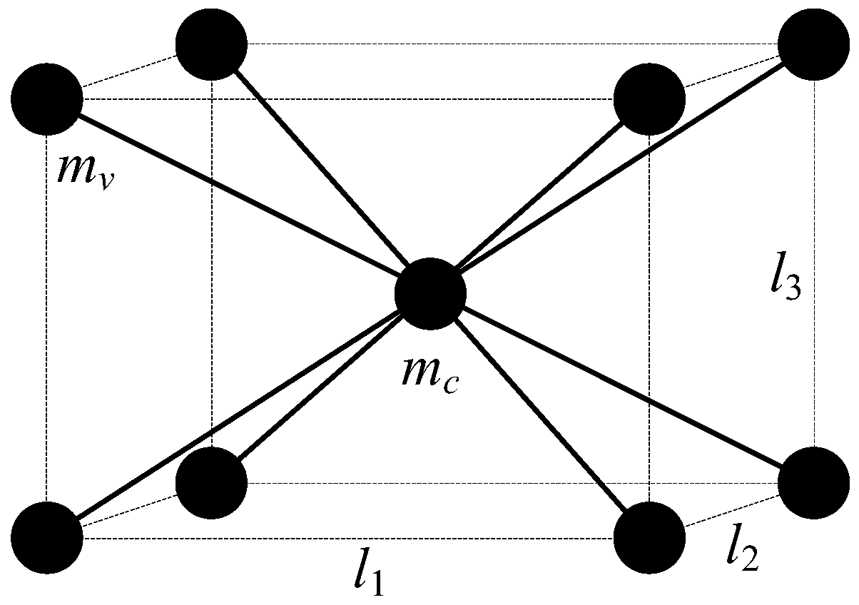
[0068] Step 101, coordinate system definition, small celestial body gravitational field calculation method, and detector discrete particle model.

[...


PUM


Abstract

The embodiment of the invention provides a small celestial body landing trajectory optimizing method considering a gravitation attitude and orbit coupling effect. The small celestial body landing trajectory optimizing method considering the gravitation attitude and orbit coupling effect comprises the steps of obtaining coordinate system definition, a small celestial body gravitational field calculation method and a detector discrete mass model; obtaining a detector six-degree-of-freedom kinetic model according to the coordinate system definition, the small celestial body gravitational field calculation method and the detector discrete mass model; using an indirect method to obtain a fuel optimal two-point-boundary-value problem model according to the detector six-degree-of-freedom kineticmodel; and using a two-stage homotopy method to calculate the fuel optimal two-point-boundary-value problem model to obtain a small celestial body landing fuel optimal trajectory considering the gravitation attitude and orbit coupling effect according to the fuel optimal two-point-boundary-value problem model. According to the technical scheme provided by the embodiment of the invention, effectivecalculation of the small celestial body landing trajectory optimizing problem can be realized to obtain a six-degree-of-freedom fuel optimal trajectory; and therefore, additional fuel consumption generated during rigid body detector trajectory tracking under the gravitation attitude and orbit coupling effect is avoided, and the fuel optimality of a landing task is guaranteed.

Description

【Technical field】 [0001] The invention relates to planetary landing technology, in particular to a small celestial body landing trajectory optimization method considering the gravitational attitude-orbit coupling effect. 【Background technique】 [0002] The landing detection and sampling return of small celestial bodies can obtain soil samples and high-resolution data, which has become one of the main forms of small celestial body detection at present. In order to prolong the life of the probe's follow-up mission, the landing trajectory planning is usually upgraded to a landing trajectory optimization problem with the goal of minimizing fuel consumption. [0003] It is worth noting that the current studies on the optimization of the landing trajectory of small celestial bodies all calculate the detector as a mass point instead of a rigid body, ignoring the influence of the gravitational attitude-orbit coupling effect on the movement of the detector. The gravitational attitud...

Claims


Application Information

Patent Timeline
IPC IPC(8): B64G1/24G06F17/50
CPCB64G1/24G06F30/20G06F2119/06B64G1/245
Inventor 陈钢蔡沛霖王一帆张龙刘丹
Owner BEIJING UNIV OF POSTS & TELECOMM
Why Eureka
Try Eureka