[0042] The technical solution of this patent will be described in further detail below in conjunction with specific embodiments.
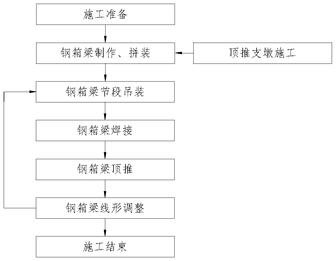
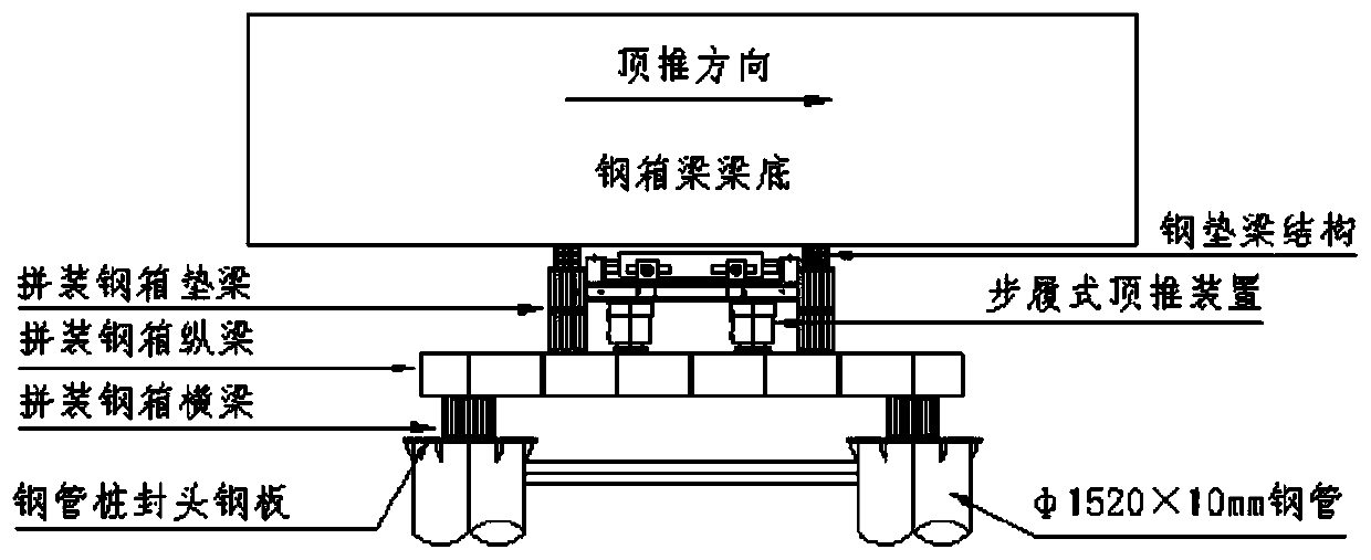
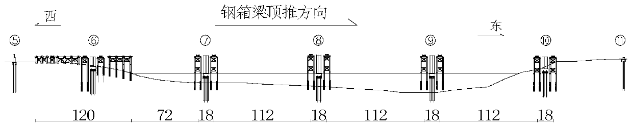
[0043] See Figure 1-4 , The assembling process of double-box composite beam structure with equal height includes the following steps:
[0044] S1, steel box girder transportation and lifting:
[0045] After the assembling and painting of the single steel box girder is completed, the finished steel box girder is transported to the steel box girder lifting area by the girder truck, and then the steel box girder is smoothly connected to the welding platform through the traverse device, and the gantry crane lifting system is used for the order The steel box girder is lifted, hoisted to the welding platform, and the plane position and elevation are adjusted in place.
[0046] S2, steel box girder installed in place
[0047] S3. When installing the first section of the steel box girder, use the gantry crane to hoist and transport the first section of the steel box girder to the corresponding position of the assembly and welding platform, lower the steel girder, and use the welding platform beam to support, and then carry out the middle section of the steel box girder. Assembly and welding of edge plates. Follow the same steps to transport the subsequent beam sections in place, review the steel beam line type, welded steel box girder middle flange plate, and seam, and start the steel box girder girth weld welding operation.
[0048] S3, steel box beam welding
[0049] The steel box girder section is welded to the guide beam or the previous section of the steel box girder after the bridge position of the jacking platform is in place, and all welds are 100% tested. After the test is qualified, it is ready for jacking.
[0050] S4, steel box girder push
[0051] The steel box girder jacking adopts the pier-on-step-type jacking equipment to realize the forward jacking of the steel box girder. The construction adopts multi-point self-balancing jacking technology. The jacking device has two sets of horizontal and vertical jack systems, which are completed separately When moving forward and lifting, apply a small horizontal force to the outside.
[0052] A supporting steel cushion beam is set between the vertical jack and the steel beam. The longitudinal contact size of the steel cushion beam supported by a single jacking device is ≥1.2m, so that the concentrated force of the jack is evenly distributed. Measures should be taken to ensure that there is no void within 1.2m and the vertical Directly align the longitudinal web of the approach bridge.
[0053] The single pushing stroke of the walking type jacking is 2m, which corresponds to the setting of a diaphragm every 2m in the box girder design structure to ensure that the box girder deformation meets the requirements.
[0054] The self-balancing jacking tool and the temporary steel backing beam form a set of jacking equipment, and the temporary steel backing beam supports the steel structure main beam when the self-balancing jacking tool returns. The temporary steel backing beam has sufficient rigidity and size to ensure that the vertical force of the interaction between the contact surface with the steel main beam can be uniformly diffused in the longitudinal direction, the diffusion range is ≥1.2m, and the vertical force must be directly transmitted to the main beam Web.
[0055] The two processes of jacking and assembling are carried out alternately. During the jacking process, real-time monitoring of jack lifting height, jacking displacement, jack hydraulic pressure and other parameters are maintained to ensure synchronized operation of all jacks.
[0056] The walking jacking equipment integrates jacking, horizontal push and horizontal adjustment, and can adjust the horizontal and vertical bridge directions. During the jacking construction process, by adjusting the stroke of the hydraulic cylinder and the jacking support cylinder by adjusting the bridge direction and the cross bridge direction, the computer control system can correct the deviation to ensure that the center line of the steel box girder is within the allowable range.
[0057] S5, falling beam
[0058] The beam drop is to lift the steel box girder pushed in place with a vertical jack, take out the pads and slides, and finally loosen the jack to steadily drop the whole beam on the design support, so that the force state of the beam after the drop beam conforms to its own weight bending When the beam is dropped, the reaction force of the support should be controlled mainly, and the elevation of the bottom of the beam should be properly considered. Preparation before beam drop:
[0059] (1) Remove or loosen the traction rope
[0060] (2) Re-measure the elevation of the bridge piers and check whether the pile foundation has settlement
[0061] (3) Clean up the plane of the bridge pier cover beam and release the constraint on the beam body.
[0062] (4) Install vertical jacks.
[0063] The principle of falling beams:
[0064] (1) Make full preparations and try to make the lifting and lowering time as short as possible;
[0065] (2) To determine the location of the jack, longitudinal and transverse symmetry is required, that is, considering the force of the pier cover beam, and considering that the force of the steel box girder body is in a favorable position;
[0066] (3) The vertical jack requires sufficient surplus jacking force and working stroke. When jacking up, the cushion stone of the bridge pier and the bottom of the box girder must have safety devices;
[0067] (4) Try to control the jacking height of the beam, pay attention to the order of jacking and landing, the jacks on a pier must rise and fall uniformly, and the jacking height of the longitudinal piers must be reasonably distributed.
[0068] The sliding box of the walking-type jacking device is a force-bearing structure supporting the main beam. The upper part is placed 2cm~5cm rubber sheet or high-density wood board, which can balance the local force of the main beam; the lower part of the sliding box is welded with a stainless steel plate to gather on the slideway The tetrafluoroethylene plate constitutes the sliding surface. The surface of the PTFE board is made into a mushroom head, and silicone oil can be applied in the middle to reduce the friction resistance of the sliding surface; four sets of correction devices with guide wheels are arranged on both sides of the slide, which can not only solve the guiding problem along the bridge, but also It can solve the adjustment problem of the transverse bridge direction; the piston heads of the four jacking jacks are equipped with ball heads, which can adapt to a small range of slope. Its performance parameters are as follows:
[0069] Performance parameter table of walking pushing equipment
[0070]
[0071] C. Power and control system
[0072] BDT walking jacking system includes five major structures and three major systems: sliding box structure, slideway structure, jacking jack structure, translation jack structure, correction device structure; hydraulic pump station system, sub-control system and master control system. The system uses the two steps of "topping" and "pushing" alternately. First, the overall steel box girder is lifted; then the steel box girder is forwarded; then the steel box girder is placed on the temporary structure of the bridge pier; the jacking cylinder is retracted to the end, Continue to achieve the next cycle. Through the cycle of reciprocating pushing steps, the steel box girder is finally sent to the predetermined position.
[0073] The main steps of walking jacking construction
[0074] S4.1. The equipment is in place;
[0075] S4.2. The sliding box touches the bridge and the vertical jack lifts up;
[0076] S4.3. Jack up the bridge and the steel beam;
[0077] S4.4. Move forward 1 pushing stroke. Steel box girder advancement;
[0078] S4.5. The bridge falls on the pad beam, and the steel box beam falls;
[0079] S4.6. The sliding box is separated from the bridge and the sliding box is lowered;
[0080] S4.7, pan and push back, and perform the next push.
[0081] The walking-type jacking supporting hydraulic pump station in the present invention uses a motor to drive a load-sensitive variable pump. The oil output from the variable pump passes through a proportional multi-way valve, and the proportional valve controls the on-off and flow rate of the oil entering each circuit Size to adjust system synchronization. The load-sensitive variable pump adjusts the angle of the variable swash plate according to the opening size of the proportional valve spool, thereby adjusting the output flow value to match the opening value of the proportional valve, thereby achieving the purpose of energy saving.
[0082] The control system adopts a distributed computer network control system, which is composed of a main console (industrial computer + configuration software), several field controllers, several sensors, several data lines and control lines.
[0083] The network composition of the walking push control system: The main control computer determines the sequence of actions of the oil cylinders according to the displacement signals and pressure signals collected by various sensors and according to certain control procedures and algorithms, and completes the coordination work of the cluster jacks. Each field controller can be remotely controlled to display the hydraulic pressure and displacement of the jack; display the lifting distance on both sides of each pier; display whether the box girder has lateral displacement. It can start and stop the pump station remotely, adjust the flow and pressure of the pump station remotely, and control the pump station to complete various actions. In the online state, all operations are completed by the main control computer, and the on-site controller only performs emergency stop operations. The system has a data storage function and a fault alarm function, and it will automatically stop when the preset stroke or load limit is reached.
[0084] Due to the objectivity of uneven load distribution and different frictional forces, when deviation occurs during the pushing process, the deviation can be corrected by the correcting jack set on the side of the slide box. When conditions permit, a limit method is adopted.
[0085] Drop beam equipment selection:
[0086] After the pusher is in place, the walking pusher must be removed first. The falling beam jack needs to consider its load capacity, sufficient reserve factor, and whether the size meets the construction requirements.
[0087] The falling beam jack is proposed to be a 500t jack.
[0088] YD5000/31.5-200 beam drop equipment performance parameter table
[0089]
[0090] Installation and layout requirements
[0091] The support surface at the bottom of the jack should be kept flat, the jack and the steel beam support must be checked for the force performance, and the support steel plate should be used to disperse the stress.
[0092] Power control and operation
[0093] It can be used to push the hydraulic pump station or electric pump station.
[0094] Technical parameters of ZB10/320-4/800 hydraulic pump station for beam drop equipment
[0095]
[0096] Selection of emergency equipment measures
[0097] Construction equipment capacity requirements
[0098] Jacks for falling beams can also be used as emergency equipment.
[0099] The risk is small, which is conducive to the alignment of the main bridge. It is installed with 4 slides and multi-point continuous pushing methods. The underwater jacking buttress uses the lower structure construction platform to connect the high temporary buttresses as the jacking buttresses, and is equipped with walking type jacking equipment. The maximum distance between the support piers is 112m, which meets the navigation requirements of Class II waterways and meets the requirements of 80m single-hole two-way navigation channels.
[0100] The walking type jacking device adopts multi-point self-balancing jacking technology. The jacking device has two sets of horizontal and vertical jack systems, which can be adjusted and corrected by horizontal jacks to ensure that the line shape and plane position of the steel box girder are consistent with the design.
[0101] The preferred embodiments of this patent are described in detail above, but this patent is not limited to the above embodiments. It can also be made without departing from the purpose of this patent within the scope of knowledge possessed by those of ordinary skill in the art. Various changes.