Two-stage walking speed reducer with brake shaft

A traveling reducer, with braking technology, applied in the direction of mechanical equipment, transmission, transmission parts, etc., can solve the problems of complex structure of reducer, unsatisfactory reducer, low efficiency of reducer, etc., to save operation space, The internal structure is novel and the output torque is large.

Inactive Publication Date: 2019-10-15
HUBEI KEFENG TRANSMISSION EQUIP CO LTD
View PDF5 Cites 1 Cited by
  • Summary
  • Abstract
  • Description
  • Claims
  • Application Information

AI Technical Summary

Problems solved by technology

Its disadvantages are: the structure of the reducer is complicated, there are many gear trains, the efficiency of the reducer is relatively low, and the internal friction will be relatively large. When braking, it needs to be equipped with some auxiliary parts such as hydraulic valves and oil pumps, and the relative cost is also low. relatively high
This reducer cannot meet the requirements of the AGV trolley steering wheel system for the reducer, so it cannot be applied to these transmission systems with special requirements

Method used


Image

  • Two-stage walking speed reducer with brake shaft
  • Two-stage walking speed reducer with brake shaft
  • Two-stage walking speed reducer with brake shaft

Examples


Embodiment 1

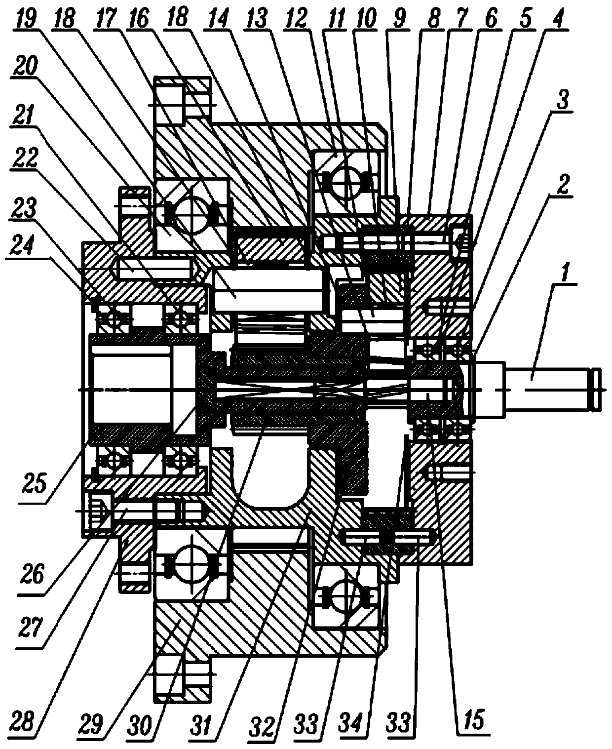
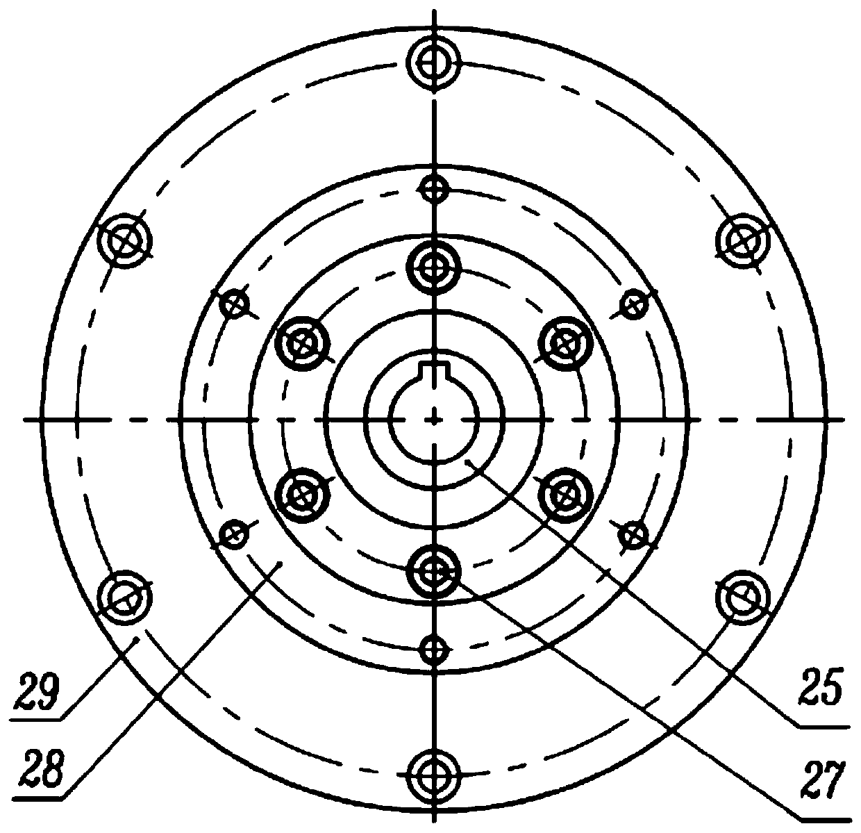
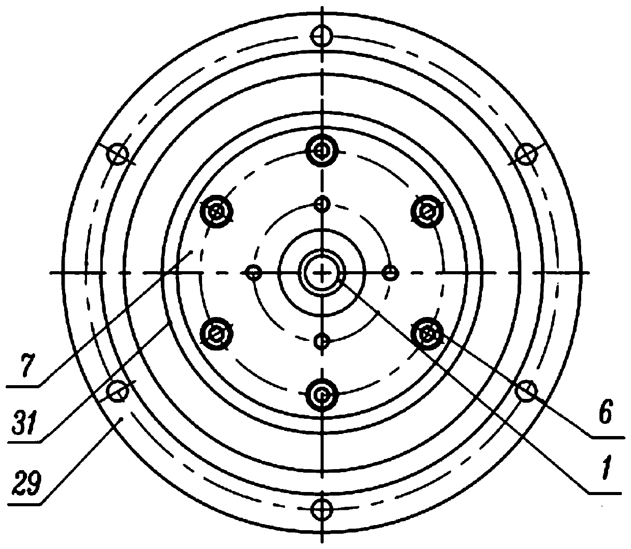
[0030] Embodiment 1: The present invention provides a double-stage travel reducer with a brake shaft, the structure of which is as follows figure 1 , 2 , as shown in 3, figure 1 It is the front view of the reducer of the present invention, figure 2 , 3 respectively figure 1 left and right views. From figure 2 At least the input shaft 25, the input flange 28 and the first-stage ring gear 29 provided on the left side of the reducer can be seen. image 3At least the brake shaft 1, the rear end cover 7 and the first-stage planet carrier 31 provided on the right side of the reducer can be seen, and the other side of the first-stage ring gear 29 can also be seen. see figure 1 , The reducer is also provided with a primary sun gear 30, a secondary sun gear 15, a secondary ring gear 8, a secondary planet carrier 32, a primary planetary gear 16 and a secondary planetary gear 9.

[0031] The input shaft 25 is provided with a first single row deep groove ball bearing 23 and a se...


PUM


Abstract

The invention relates to a two-stage walking speed reducer with a brake shaft. One end of a primary planet carrier in a speed reducer is connected with a secondary gear ring and a rear end cover, andthe other end of the primary planet carrier is connected with an input flange; one end of a secondary sun wheel is arranged on an input shaft, and the other end of the secondary sun wheel is arrangedon a brake shaft, the input shaft, the secondary sun gear and the brake shaft are coaxially arranged; a primary sun wheel is arranged on the secondary planetary carrier, the primary planetary gear andthe primary sun gear are in external meshing gear transmission, a secondary planetary gear and the secondary sun gear are in external meshing gear transmission, the primary planetary gear and the secondary planetary gear are connected with a primary gear ring and the secondary gear ring respectively, and the secondary gear ring is in transmission with an inner-meshing gear; and a secondary gear transmission part is a planetary gear train, and a primary gear transmission part is a fixed-shaft gear train. The input shaft of the speed reducer is input, the primary gear ring and the brake shaft are simultaneously output, and the brake shaft and the input shaft rotate in the same direction at the same speed. The speed reducer is compact in structure, short in axial size, small in size, large in transmission ratio, large in output torque and high in radial bearing capacity, and is most suitable for a steering wheel system of an AGV trolley.

Description

technical field [0001] The invention relates to a double-stage travel reducer with a brake shaft, specifically a double-stage travel reducer with a brake shaft, which is composed of a planetary gear train and a fixed-axis gear train, and belongs to the technical field of mechanical transmission . Background technique [0002] The travel reducer is an ideal driving device for wheeled or crawler-driven vehicles and other mobile equipment. It is a widely used industrial product that can reduce the speed of the motor and increase the output torque. The traditional travel reducer is mostly used for Excavator track drives, airport vehicle wheel drives, waste compactor vehicle wheel drives, harvester wheel drives, road roller travel drives and drilling equipment track drives. However, the traditional travel reducer has a relatively simple structure, and the output mode is: input shaft input, ring gear output, which is not suitable for the transmission system of some AGV trolleys t...

Claims


Application Information

Patent Timeline
Patent Type & Authority Applications(China)
IPC IPC(8): F16H1/32F16H57/023F16H57/08F16H57/10
CPCF16H1/32F16H57/023F16H57/082F16H57/10F16H2001/324F16H2001/325
Inventor 吴俊峰凌浩然
Owner HUBEI KEFENG TRANSMISSION EQUIP CO LTD
Why Eureka
Try Eureka