
Piezoelectric self-energizing-based rotated mechanical rotor vibration wireless measurement system

A technology for rotating machinery and rotor vibration, applied in the testing of mechanical components, generators/motors, piezoelectric effect/electrostrictive or magnetostrictive motors, etc., can solve the problem of high oil temperature in bearing oil chambers and insufficient structural space , Arrangement of acceleration vibration sensors and other issues, to achieve the effect of simple arrangement structure, solving the problem of insufficient space arrangement and complex arrangement, and accurate measurement information

Pending Publication Date: 2019-10-15
中国船舶重工集团公司第七0三研究所
View PDF0 Cites 0 Cited by
  • Summary
  • Abstract
  • Description
  • Claims
  • Application Information

AI Technical Summary

Problems solved by technology

[0003] The technical problem to be solved by the present invention is: in the existing measurement method, due to the compact rotor support structure, high oil temperature in the bearing oil chamber and insufficient structural space, it is difficult to wire on the rotor support structure, so it is difficult to install the rotor bearing seat of the engine. Acceleration vibration sensors are arranged nearby; and then a piezoelectric self-powered wireless measurement system for rotor vibration of rotating machinery is provided

Method used


Image

  • Piezoelectric self-energizing-based rotated mechanical rotor vibration wireless measurement system
  • Piezoelectric self-energizing-based rotated mechanical rotor vibration wireless measurement system
  • Piezoelectric self-energizing-based rotated mechanical rotor vibration wireless measurement system

Examples


specific Embodiment approach 1

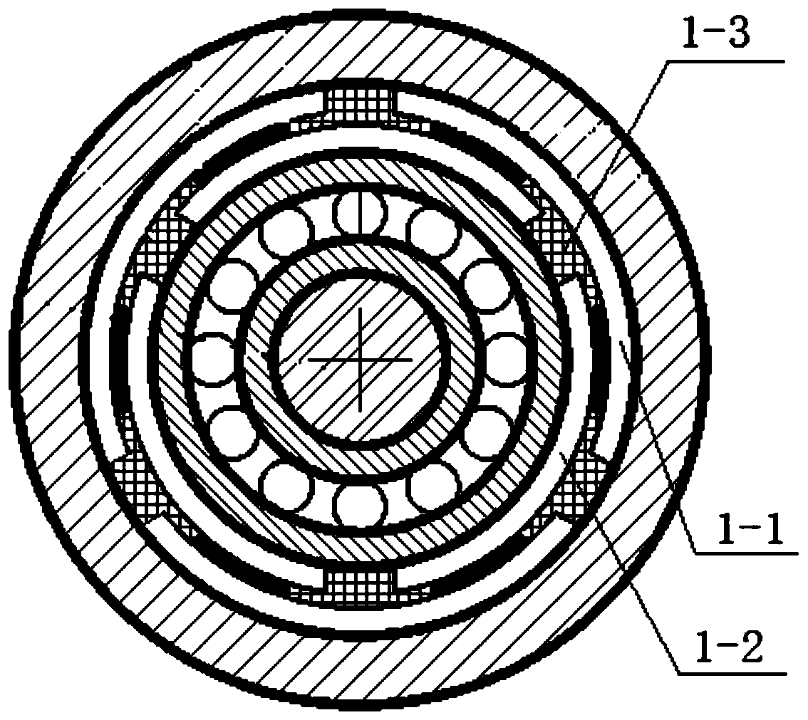
[0016] Specific implementation mode one: as figure 1 As shown, in this embodiment, the rotating machinery rotor vibration wireless measurement system includes a ring-type elastic support 1, a support base 3, a bearing 5, a voltage conversion vibration module 6, a piezoelectric energy distribution module 7, and a wireless signal transmission module 8. Wireless signal receiving module 9. Vibration signal acquisition and analysis module 10. Multiple wires and multiple piezoelectric bodies 2. The bearing 5 is set outside the rotor 4. The ring-type elastic support 1 is set outside the outer ring of the bearing 5. The support base The seat 3 is set outside the ring-type elastic support 1, and the piezoelectric body 2 is fixed on the ring-type elastic support 1. Each piezoelectric body 2 is connected to the voltage conversion vibration module 6 and the piezoelectric energy distribution module 7 through two wires respectively. Connection, the signal output end of the voltage conversio...

specific Embodiment approach 2

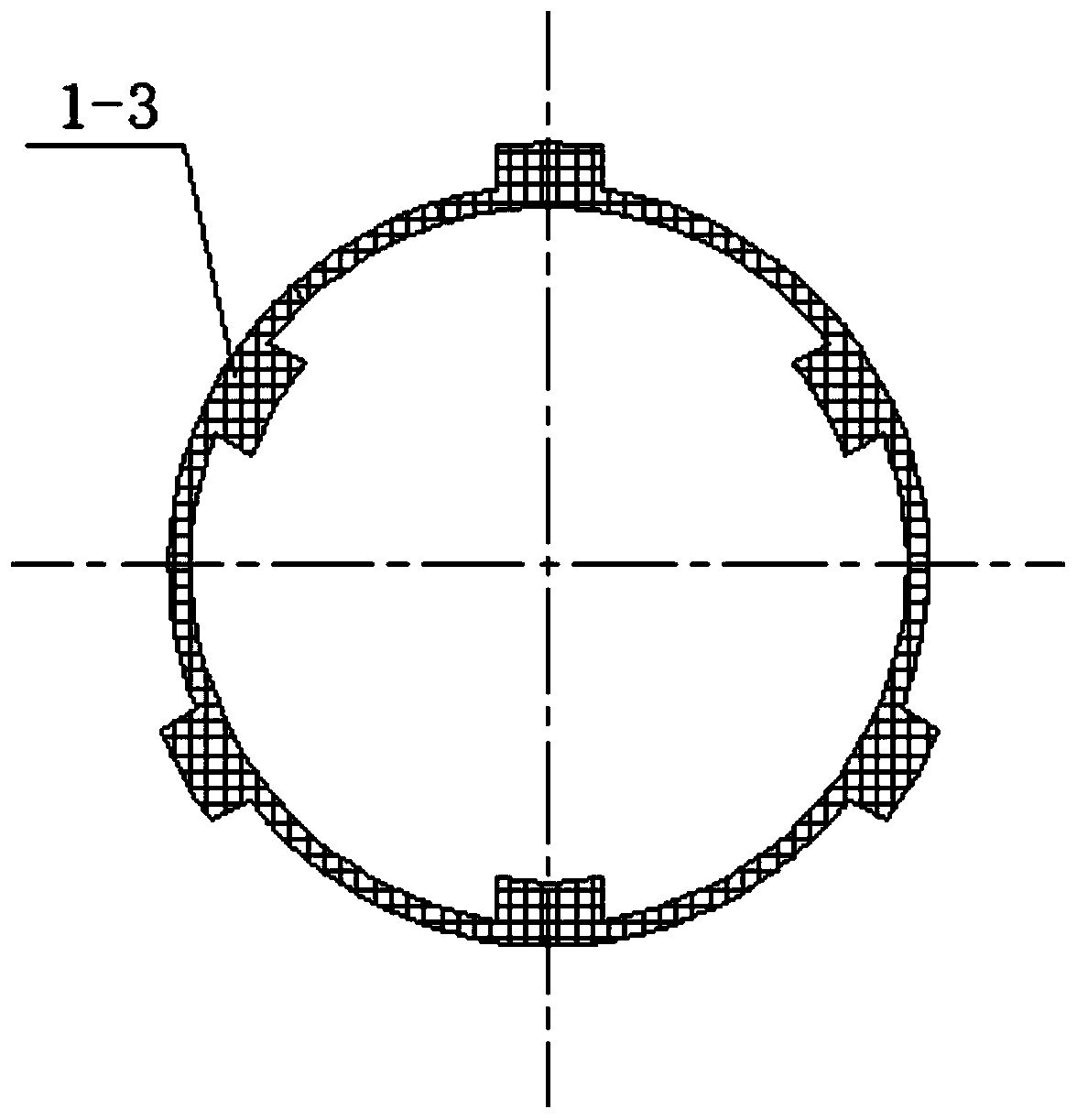
[0021] Specific implementation mode two: as figure 2 and image 3 As shown, in this embodiment, the ring-type elastic support 1 includes a deformation body 1-3, a plurality of outer bosses 1-1 and a plurality of inner bosses 1-2, and the outer bosses 1-1 and inner bosses The platforms 1-2 are all arc-shaped plates, and the number of the outer bosses 1-1 and the inner bosses 1-2 is the same, and a plurality of inner bosses 1-2 are evenly spaced in the circumferential direction to form a first ring. The outer bosses 1-1 are evenly spaced in the circumferential direction to form a second ring, the second ring is set on the outside of the first ring, and each outer boss 1-1 and each inner boss 1-2 Displaced between the two, the deformation body 1-3 is respectively filled between the outer boss 1-1 and the inner boss 1-2, between two adjacent inner bosses 1-2 and adjacent two outer bosses 1 Between -1, the piezoelectric body 2 is fixedly connected to the deformable body 1-3.

...

specific Embodiment approach 3

[0024] Specific implementation mode three: as figure 1 and figure 2 As shown, in this embodiment, the number of piezoelectric bodies 2 is twice the number of inner bosses 1-2, and each piezoelectric body 2 is located between adjacent outer bosses 1-1 and inner bosses 1 respectively. -2, and one end surface of the piezoelectric body is in contact with the inner surface of one end of the outer boss, and the other end surface of the piezoelectric body is in contact with the outer surface of one end of the inner boss, wherein the inner boss 1- The number of 2 is 3, the number of outer bosses 1-1 is 3, and the number of piezoelectric bodies is 6.

[0025] Other composition and connection methods are the same as those in Embodiment 2.


PUM


Abstract

A piezoelectric self-energizing-based rotated mechanical rotor vibration wireless measurement system belongs to an energy power industry. In existing rotor vibration measurement, a rotor support structure is compact and a structural space is insufficient so that wiring on the rotor support structure is difficult. In the invention, the above problem is solved. A bearing sleeves an outer portion ofa rotor, a ring-type elastic support sleeves the outer portion of the bearing, a support pedestal sleeves the outer portion of the ring-type elastic support, and a piezoelectric body is fixedly installed on the ring-type elastic support. Each piezoelectric body is connected to a voltage conversion vibration module and a piezoelectric energy distribution module through two leads. A signal output end of the voltage conversion vibration module is connected to a signal input end of a wireless signal transmission module through the lead. The piezoelectric energy distribution module is connected tothe wireless signal transmission module through the lead, and a wireless signal receiving module is connected to a vibration signal collecting and analyzing module through the lead. The system is mainly used for measuring rotor vibration.

Description

technical field [0001] The invention belongs to the energy and power industry, and in particular relates to a piezoelectric self-supplied energy-based wireless measurement system for rotor vibration of rotating machinery. Background technique [0002] Due to the complex structure and compact layout of the rotor support system of high-speed rotating machinery such as aero-engines and gas turbines, it is often impossible to directly measure the vibration characteristics of the rotor. At present, most of the methods are based on the vibration transmission characteristics of the rotor support system of the engine and the stator casing, and the vibration acceleration sensor is arranged at a specific position of the corresponding casing, because the vibration characteristics of the supporting structure and the stator casing itself will give The vibration signal of the rotor brings large noise, which makes it difficult to measure and extract some vibration characteristics of the ro...

Claims


Application Information

Patent Timeline
Patent Type & Authority Applications(China)
IPC IPC(8): G01M13/00G01H17/00H02N2/18G08C17/02
CPCG01M13/00G01H17/00H02N2/186G08C17/02
Inventor 徐宁何鹏刘勋
Owner 中国船舶重工集团公司第七0三研究所
Learn More