Eureka AIR delivers breakthrough ideas for toughest innovation challenges, trusted by R&D personnel around the world.

Straw treatment system and treatment method

A processing system and straw technology, applied in the field of agricultural machinery, can solve the problems of small proportion of straw, large turning radius, and reduced straw workload.

Active Publication Date: 2019-10-18
NANJING AGRI MECHANIZATION INST MIN OF AGRI
View PDF7 Cites 2 Cited by
  • Summary
  • Abstract
  • Description
  • Claims
  • Application Information

AI Technical Summary

Problems solved by technology

[0002] The resource utilization of straw is a very good way to deal with straw, but subject to various conditions, the proportion of straw resource utilization is very small
Straw returning to the field is the current mainstream straw treatment method, but after many years of straw returning to the field, it will damage the nutrients in the soil, affect the growth of crops, and lead to the decline of crop resistance to insects and disasters; straw burning is a very simple treatment way, but straw burning will cause a lot of pollution, so the country prohibits straw burning
[0003] For this reason, a model of direct carbonization in the field is proposed. The carbonized biochar can be easily transported and post-processed, which reduces the workload in the process of straw resource utilization. The current model of direct carbonization in the field uses straw The carbonization system is used for processing. The straw carbonization system generally includes processing equipment such as picking up, conveying, and high-temperature carbonization that are connected together. Taking corn straw as an example, the common four-row harvesting equipment harvests 5-7 mu of land per hour, and the straw processed per hour The capacity is more than 2 tons. The carbonization system that matches this capacity occupies a large area, is bulky and heavy. When walking in the field, it faces problems such as large turning radius and slow walking speed, resulting in low efficiency of straw treatment.

Method used


Image

  • Straw treatment system and treatment method
  • Straw treatment system and treatment method
  • Straw treatment system and treatment method

Examples


Embodiment Construction

[0057] The technical solutions of the present invention will be clearly and completely described below in conjunction with the accompanying drawings. Apparently, the described embodiments are some of the embodiments of the present invention, but not all of them. Based on the embodiments of the present invention, all other embodiments obtained by persons of ordinary skill in the art without making creative efforts belong to the protection scope of the present invention.

[0058]In the description of the present invention, it should be noted that the terms "center", "upper", "lower", "left", "right", "vertical", "horizontal", "inner", "outer" etc. The indicated orientation or positional relationship is based on the orientation or positional relationship shown in the drawings, and is only for the convenience of describing the present invention and simplifying the description, rather than indicating or implying that the referred device or element must have a specific orientation, o...


PUM


Abstract

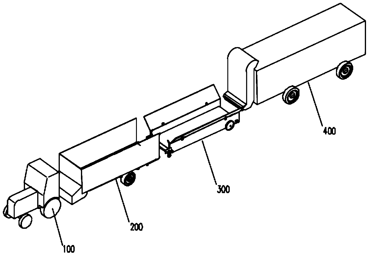
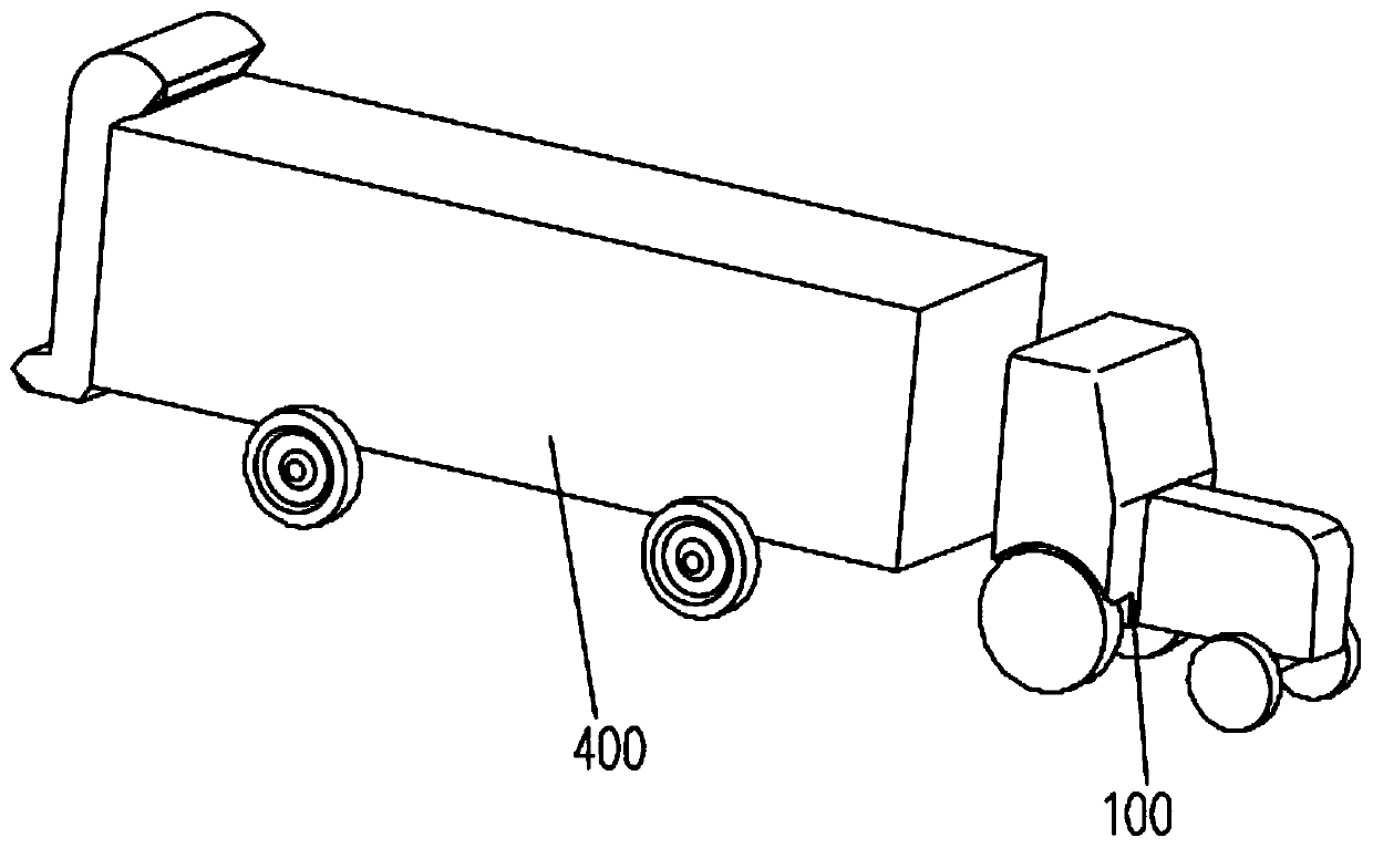
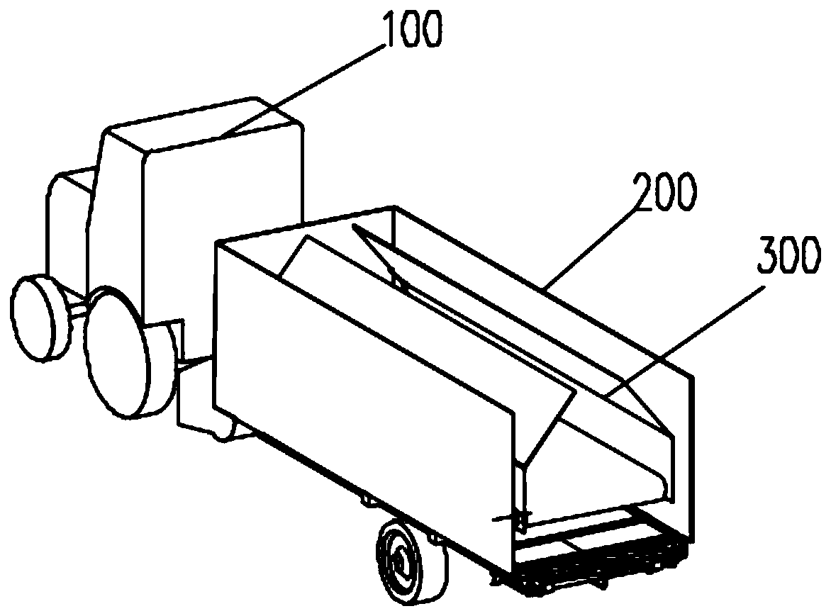
The invention provides a straw treatment system and a treatment method, and belongs to the field of agricultural machinery. The straw treatment system comprises traction equipment, a pick-up trailer,conveying equipment and carbonizing equipment; the traction equipment is used for driving the pick-up trailer and the carbonizing equipment to move to a working site; the pick-up trailer is used for loading or unloading the conveying equipment, and pulled by the traction equipment to pick up straw after the conveying equipment is unloaded; the conveying equipment is used for receiving the straw unloaded by the pick-up trailer and conveying the straw into the carbonizing equipment; the carbonizing equipment is used for carbonizing the straw. According to the straw treatment system and the treatment method, through the reasonable arrangement of the traction equipment, the pick-up trailer, the conveying equipment and the carbonizing equipment, the semi-fixed treatment mode for straw carbonizing treatment is achieved, the overall size and weight are reduced, the turning radius during walking is reduced, the conveying flexibility and the walking speed are improved, and the efficiency of treating the straw is significantly improved.

Description

technical field [0001] The invention relates to the field of agricultural machinery, in particular to a straw processing system and processing method. Background technique [0002] The resource utilization of straw is a very good way to deal with straw, but subject to various conditions, the proportion of straw resource utilization is very small. Straw returning to the field is the current mainstream straw treatment method, but after many years of straw returning to the field, it will damage the nutrients in the soil, affect the growth of crops, and lead to the decline of crop resistance to insects and disasters; straw burning is a very simple treatment way, but straw burning will cause a lot of pollution, so the state prohibits straw burning. [0003] For this reason, a model of direct carbonization in the field is proposed. The carbonized biochar can be easily transported and post-processed, which reduces the workload in the process of straw resource utilization. The curr...

Claims


Application Information

Patent Timeline
IPC IPC(8): A01D89/00C10B53/02B62D49/00B62D53/00B62D59/02
CPCA01D89/001B62D49/00B62D53/00B62D59/02C10B53/02Y02E50/10
Inventor 王振伟陈明江陈永生韩柏和赵维送谢虎平英华刘先才王鹏军
Owner NANJING AGRI MECHANIZATION INST MIN OF AGRI
Why Eureka
Eureka Blog
Learn More