
Mopping device and sanitation equipment

A mop and mop technology, applied in the field of environmental sanitation and cleaning, can solve the problems of small suction diameter, large power loss, affecting the service life of the ground, etc.

Active Publication Date: 2019-10-18
山东浩睿智能科技有限公司
View PDF9 Cites 3 Cited by
  • Summary
  • Abstract
  • Description
  • Claims
  • Application Information

AI Technical Summary

Problems solved by technology

[0003] (1) The water consumption is very large, and the water tank needs to be replenished in time, which wastes time and water resources, and the efficiency of mopping the floor is low;
[0004] (2) For the collection of the sewage mixture after washing, it is necessary to use a high-power motor to drive the evacuation fan, and use the negative pressure to collect the sewage mixture through the suction cup, and the power loss is large;
[0005] (3) The suction diameter of the suction cup is relatively small, and it can only collect liquid and relatively small-diameter garbage, which has great restrictions on the types of garbage in the work area;
[0006] (4) When working on floors such as painted floors, wooden floors, and plastic materials in the workshop, because the working principle is to wash and grind the ground, it will seriously affect the service life of the ground

Method used


Image

  • Mopping device and sanitation equipment
  • Mopping device and sanitation equipment
  • Mopping device and sanitation equipment

Examples


Embodiment Construction

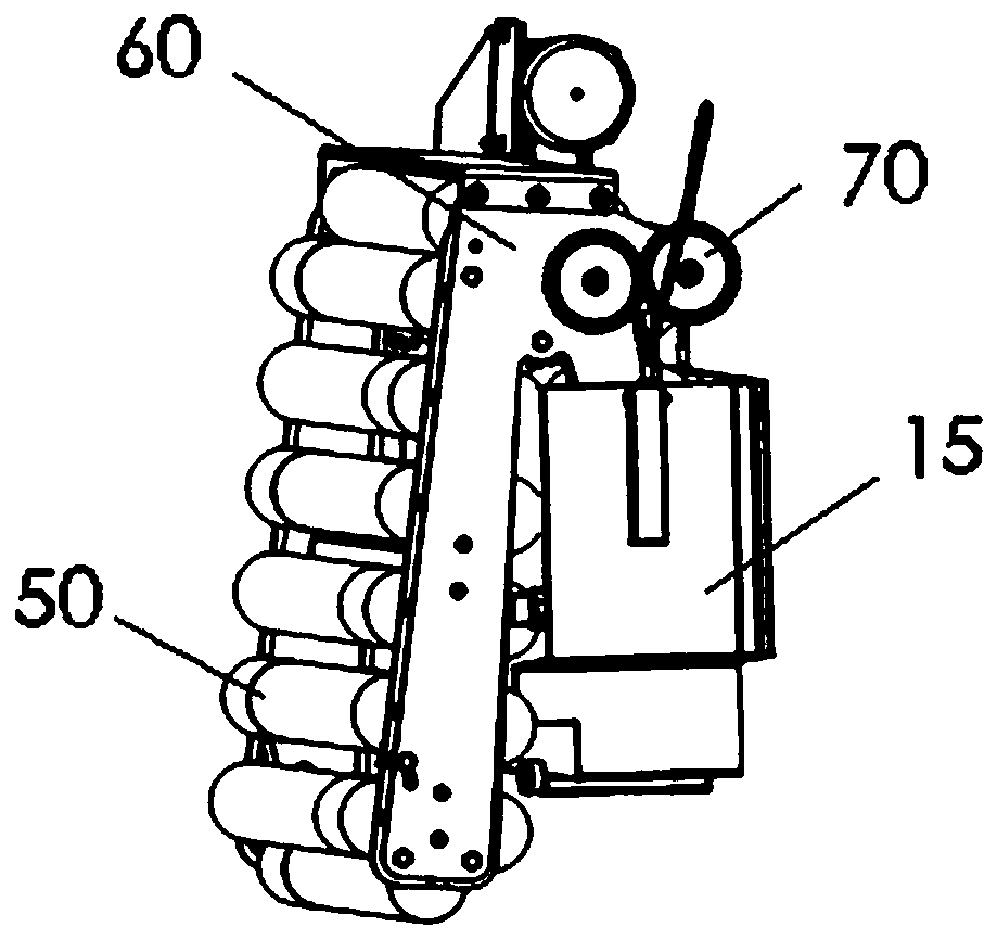
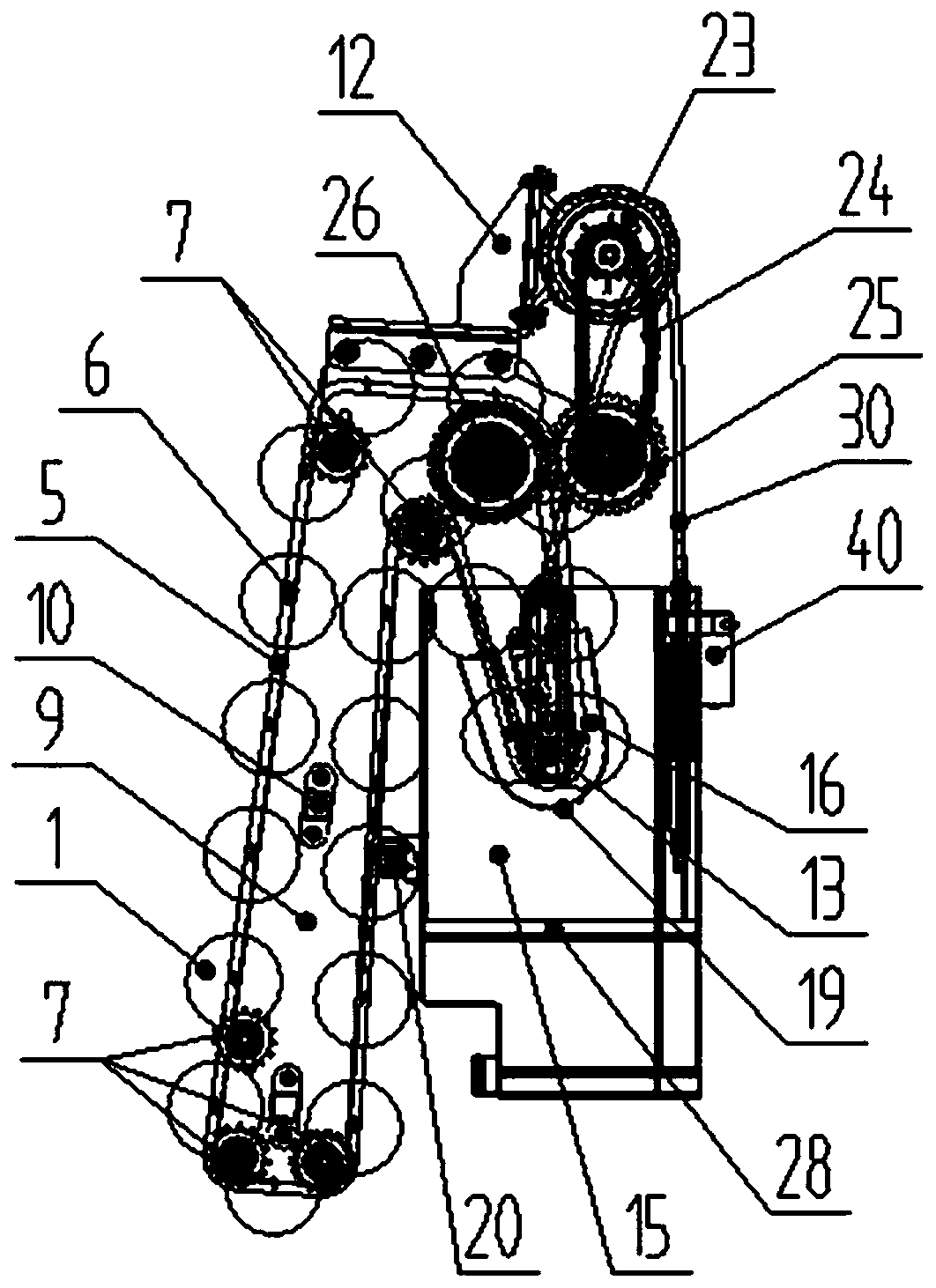
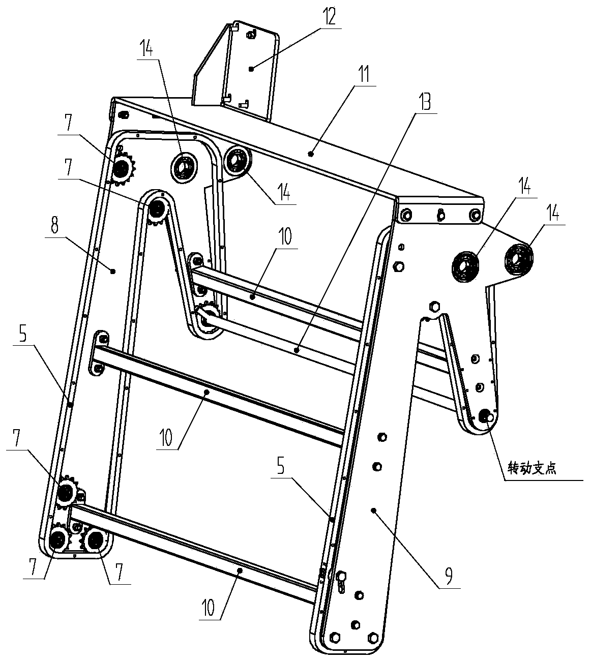
[0049] This disclosure provides a floor mopping device for sanitation machinery, aiming to solve the problems in the prior art mentioned in the above technical background, and to provide an innovative mopping device for sanitation machinery that can automatically cycle cleaning and dehydration The trace removal device can be loaded on various sanitation vehicles or equipment to work together.

[0050] In order to make the purpose, technical solutions and advantages of the present disclosure clearer, the present disclosure will be further described in detail below in conjunction with specific embodiments and with reference to the accompanying drawings.

[0051] Certain embodiments of the present disclosure will be described more fully hereinafter with reference to the accompanying drawings, in which some but not all embodiments are shown. Indeed, various embodiments of the disclosure may be embodied in many different forms and should not be construed as limited to the embodimen...


PUM


Abstract

The invention provides a mopping device. The mopping device comprises a mop cloth support assembly, a split multi-brush circulation mop, a washing water tank and a diameter-variable roller mop cloth dewatering device, wherein the mop cloth support assembly comprises a mopping operation part and a washing dewatering part, the bottom of the mopping operation part extends towards the ground, and thebottom of the washing dewatering part extends into the washing water tank; the split multi-brush circulation mop comprises multiple brush supporting shafts sleeved with brushes, the brush supporting shafts are arranged on guiding chain wheels through a roller conveying chain, and the guiding chain wheels are arranged according to a predetermined track on the mop cloth support assembly; the washingwater tank is arranged below the washing dewatering part of the mop cloth support assembly and is used for washing the split multi-brush circulation mop; and the diameter-variable roller mop cloth dewatering device is arranged above the washing water tank and is used for dewatering the split multi-brush circulation mop. The mopping device can realize automatic cyclic cleaning and wringing of mopcloth, has a good mopping effect, does not need to directly sprinkle water on the ground or the mop in operation, has the advantages of protecting the ground and saving water and is high in mopping efficiency.

Description

technical field [0001] The present disclosure relates to the field of environmental sanitation and cleaning, in particular to a floor mopping device and environmental sanitation equipment. Background technique [0002] At present, most of the ground cleaning machines used in public places such as shopping malls, hospitals, stations, and production workshops include mopping and washing devices. The working steps are generally that the front-end sprinkler mechanism sprays water continuously on the ground or mopping tools in advance. Use the rotating brush plate at the front end to rub and scrub the ground, and then collect the washed sewage by the wiper suction cup. There are following technical defects in the existing mopping and washing device: [0003] (1) The water consumption is very large, and the water tank needs to be replenished in time, which wastes time and water resources, and the efficiency of mopping the floor is low; [0004] (2) For the collection of the sewa...

Claims


Application Information

Patent Timeline
IPC IPC(8): A47L11/282A47L11/40
CPCA47L11/282A47L11/40A47L11/4041A47L11/4061
Inventor 刘成东陈开令胡广晓陈现燕徐晓飞
Owner 山东浩睿智能科技有限公司
Learn More