Flue gas denitration catalytic reactor
A catalytic reactor and catalytic reaction technology, applied in the field of flue gas denitrification, can solve the problem of low utilization rate of catalysts, and achieve the effects of facilitating mass production, increasing the duration of action, and reducing pressure.
- Summary
- Abstract
- Description
- Claims
- Application Information
AI Technical Summary
Problems solved by technology
Method used
Image

Examples
Embodiment 1
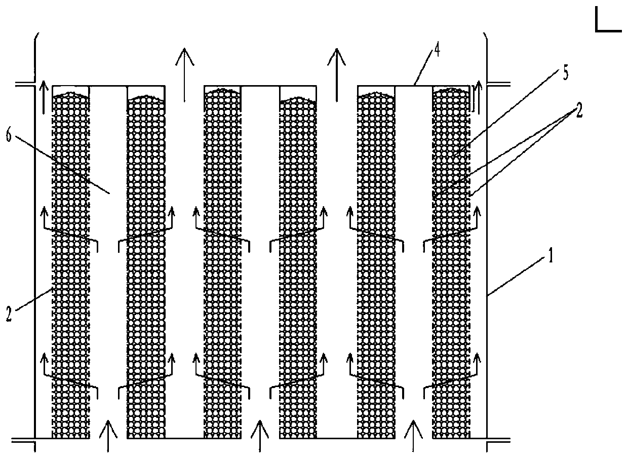
[0064] Such as Figure 5 , 6 , the catalytic reaction unit 2 in the catalytic reactor is vertically arranged, the catalytic reaction unit 2 is cylindrical, and the shell 1 of the final catalytic reactor is also cylindrical.
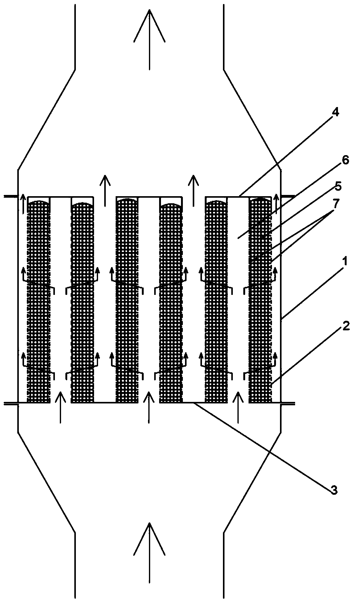
[0065] In this implementation, the adjacent cylindrical catalytic reaction units 2 are connected through the upper connecting plate and the lower connecting plate, and the upper connecting plate and the lower connecting plate are arranged alternately from the inner wall of the housing 1 to the center, and the expansion unit is expanded according to the needs of use. Reactor, determine the number of corresponding catalytic reaction unit 2. The flue gas in the flue first enters the air inlet at the bottom of the shell 1 from the flue gas denitrification catalytic reactor, and then enters from the corresponding lower air intake channel described on the upper connecting plate, crosses the catalyst layer 5 according to the internal design direction, and passe...
Embodiment 2
[0069] Such as Figure 5 , 7 , the catalytic reaction unit 2 in the catalytic reactor is vertically arranged, the catalytic reaction unit 2 is plate-shaped, and the shell 1 of the catalytic reactor finally constitutes a cuboid shape.
[0070] In this implementation, the adjacent cylindrical catalytic reaction units 2 are connected through the upper connecting plate and the lower connecting plate, and the upper connecting plate and the lower connecting plate are arranged alternately from the inner wall of the housing 1 to the center, and the expansion unit is expanded according to the needs of use. Reactor, determine the number of corresponding catalytic reaction unit 2. The flue gas in the flue first enters the air inlet at the bottom of the shell 1 from the flue gas denitrification catalytic reactor, and then enters from the corresponding lower air intake channel described on the upper connecting plate, crosses the catalyst layer 5 according to the internal design direction,...
Embodiment 3
[0074] Such as Figure 8 , 9 , the catalytic reaction unit 2 in the catalytic reactor is formed by connecting multiple groups of catalytic reaction units 2 with a herringbone shape in section, and each catalytic reaction unit 2 is plate-shaped, and the shell 1 of the catalytic reactor finally constitutes a cuboid shape .
[0075] In this embodiment, the catalytic reaction unit 2 is arranged in a slanted plate shape, and the catalytic reaction unit 2 in the housing 1 of the catalytic reactor is, from the outside to the inside, connected to the inner wall of the housing 1 of the catalytic reaction unit 2 at the bottom end, The tops of the catalytic reaction units 2 are connected, and the bottoms of the catalytic reaction units 2 are connected.
[0076] In this implementation, the adjacent cylindrical catalytic reaction units 2 are connected through the upper connecting plate and the lower connecting plate, and the upper connecting plate and the lower connecting plate are arran...
PUM
 Abstract
Description
Claims
Application Information
 - R&D
- Intellectual Property
- Life Sciences
- Materials
- Tech Scout
- Unparalleled Data Quality
- Higher Quality Content
- 60% Fewer Hallucinations
Browse by: Latest US Patents, China's latest patents, Technical Efficacy Thesaurus, Application Domain, Technology Topic, Popular Technical Reports.
© 2025 PatSnap. All rights reserved.Legal|Privacy policy|Modern Slavery Act Transparency Statement|Sitemap|About US| Contact US: help@patsnap.com