Numerical control gear grinding machine

A gear grinding machine and grinding wheel technology, applied in the direction of gear cutting machines, gear teeth, mechanical equipment, etc., can solve problems such as difficulty in ensuring machining accuracy, affecting loading and unloading of workpieces, and easy dripping of grinding fluid, so as to achieve easy chip removal and reduce Ease of waste, observation and operation

Pending Publication Date: 2019-10-18
HUNAN ZDCY (ZHONGDA CHUANG YUAN) CNC EQUIP CO LTD
View PDF0 Cites 4 Cited by
  • Summary
  • Abstract
  • Description
  • Claims
  • Application Information

AI Technical Summary

Problems solved by technology

[0003] a. In order to ensure that the movement axes do not interfere with each other and the grinding wheel can reach the processing point of the workpiece, the overhang of the grinding wheel must be long, and the overhang of the main shaft of the grinding wheel will lead to poor rigidity, so that the grinding wheel is easy to vibrate when the processing intensity is high , it is difficult to guarantee the machining accuracy;
[0004] b. The B-axis is a cradle structure, and the workpiece processing point is located directly above the A-axis turntable. During the processing, it is easy to accumulate wear debris, and during the grinding process, the grinding fluid is easy to drip onto the body, causing the body It is easy to accumulate oil, not only the cleanliness is low, but also the waste of grinding fluid is caused;
[0005] c. The position of the processed workpiece is between the two rotating supports of the B axis, which affects the loading and unloading of the workpiece and the observation during processing;
[0006] d. Set the support column on the fuselage, set the X-axis slide table on the support column, set the Z-axis slide table on the X-axis slide table, set the Y-axis slide table on the axis slide table, and finally set the C-axis on the Y-axis slide table. There are four motion axes distributed above the workpiece spindle, which is prone to top-heavy situations and poor stability;
[0007] e. The grinding wheel needs to be trimmed after being used for a period of time. When trimming, the grinding wheel must be disassembled, which is time-consuming and laborious

Method used


Image

  • Numerical control gear grinding machine
  • Numerical control gear grinding machine
  • Numerical control gear grinding machine

Examples


Embodiment 1

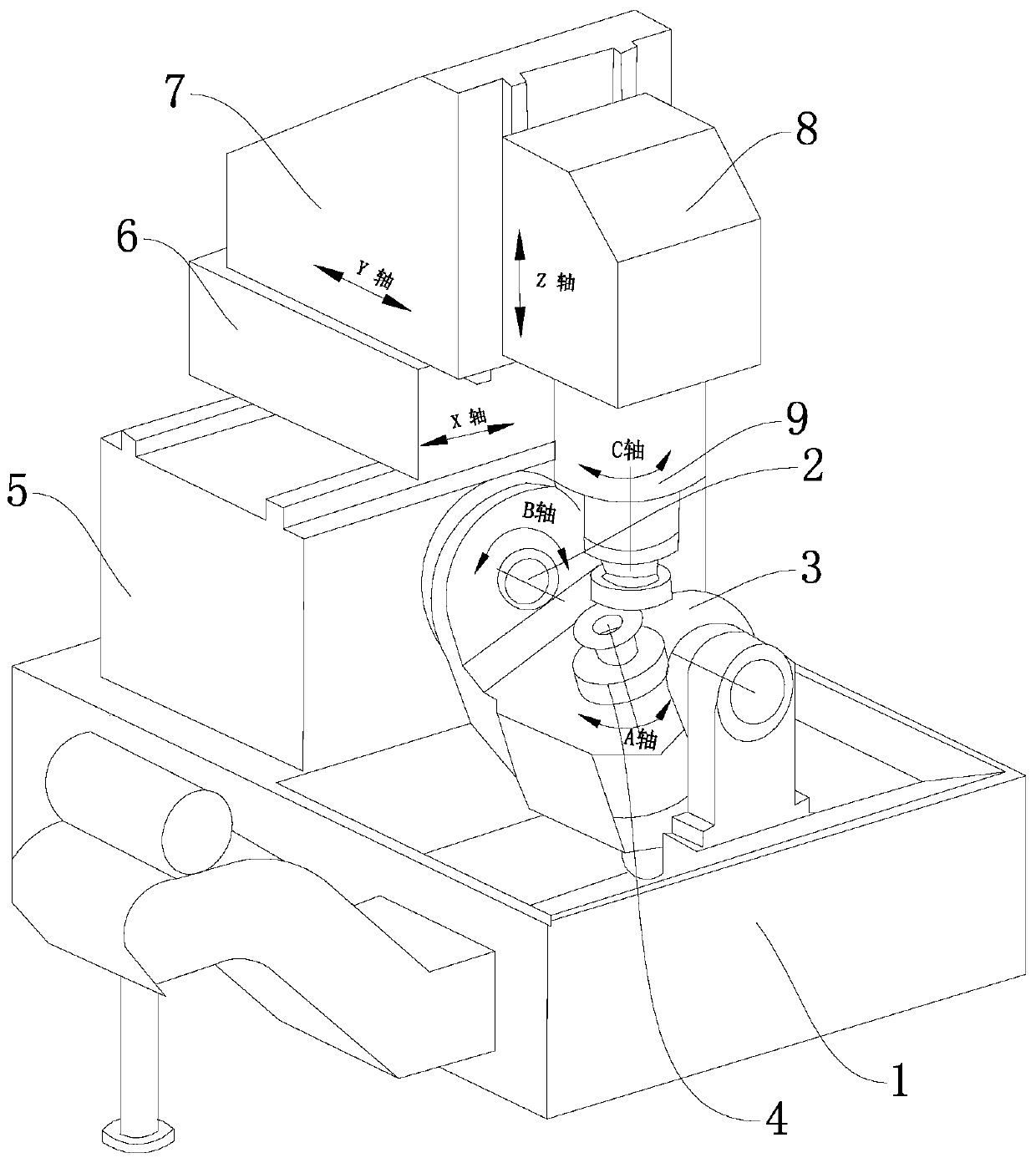
[0032] Such as Figure 2 to Figure 4 As shown, a numerically controlled gear grinding machine of the present invention includes a bed 100, on which a slide table 200 is movably arranged along the horizontal axis X-axis, and on the slide table 200 is movably arranged along the horizontal axis Z-axis A column 201 is provided, and a grinding wheel box 202 is movably arranged on the side wall of the column 201 along the vertical axis Y axis, and a grinding wheel spindle C axis is rotatably arranged in the grinding wheel box 202, and the C axis of the grinding wheel spindle is in the direction of the Z axis. Parallel, one end of the C-axis of the grinding wheel spindle is equipped with a grinding wheel 203 for processing workpieces, and the bed 100 is also provided with a rotary shaft box 204, which is located on one side of the slide table 200 along the Z-axis direction, and the rotary shaft box The body 204 is rotatably provided with a rotary shaft B shaft, the rotary shaft B sha...

Embodiment 2

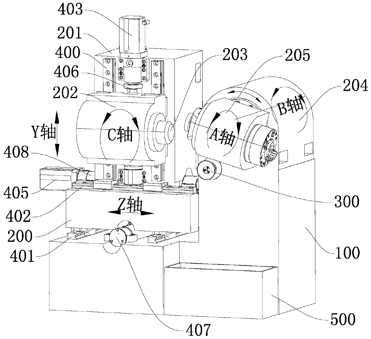
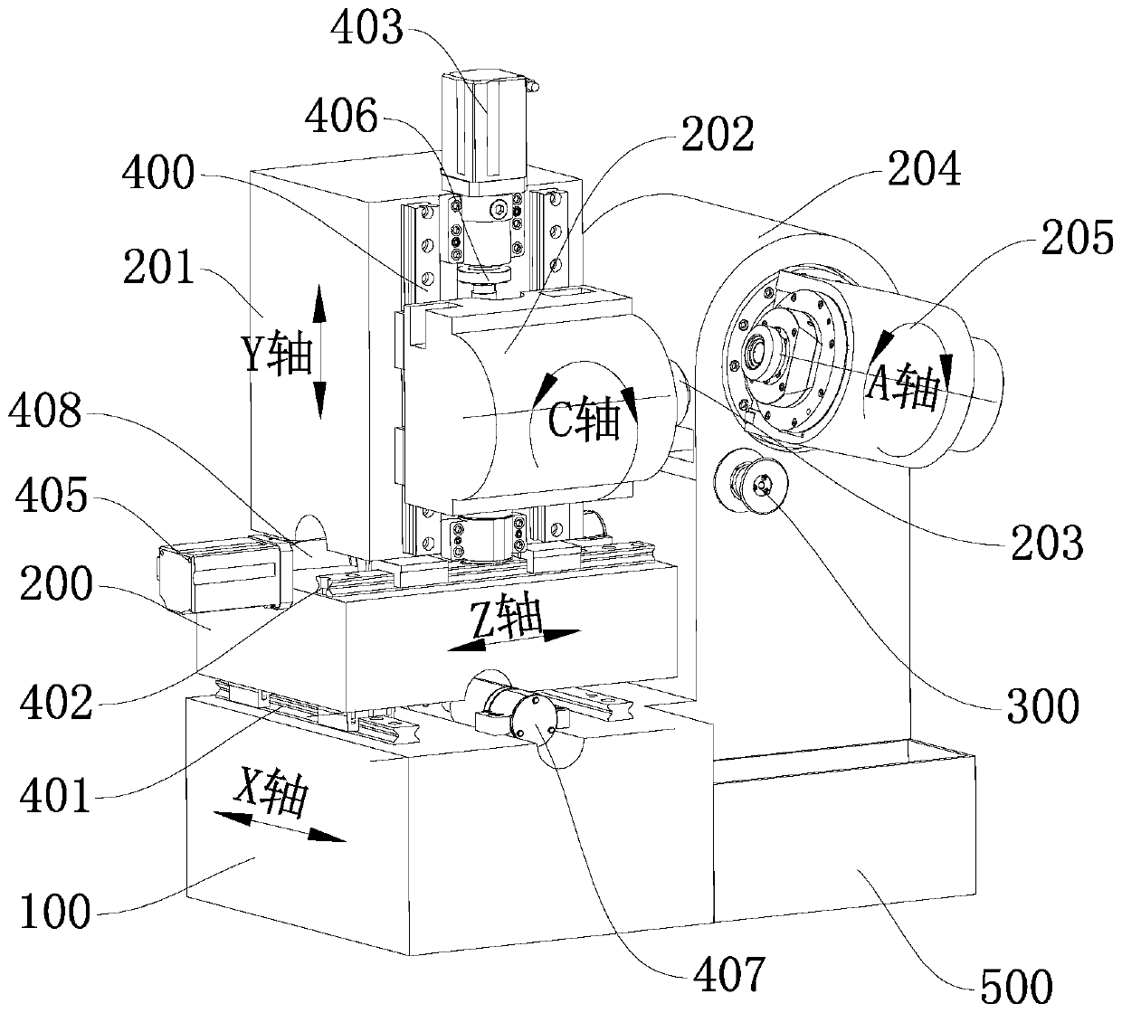
[0048] Such as Figure 5 to Figure 7 As shown, the CNC gear grinding machine provided by this embodiment is basically the same as that of Embodiment 1, the main difference lies in the connection method between the column 201 and the slide table 200 and the installation position of the grinding wheel dresser 300 in this embodiment. One makes a difference. In the first embodiment, two third guide rails 402 are horizontally arranged on the upper surface of the slide table 200, and the upright column 201 is slidably arranged on the third guide rails 402. In this embodiment, there are at least two third guide rails 402 respectively provided on the slide table On the upper surface of 200 and the side close to the tool box 202, the lower end of the column 201 and the side wall away from the tool box 202 are provided with a first opening along the Z-axis direction, so that the cross-section of the column 201 along the Z-axis direction is inverted. The ladder-like structure is used fo...


PUM


Abstract

The invention discloses a numerical control gear grinding machine. The numerical control gear grinding machine comprises a machine bed, and a sliding table is movably arranged on the machine bed alongthe axis X. A stand column is movably arranged on the sliding table along the axis Z. a grinding wheel box is movably arranged on the side wall of the stand column along the axis Y. A grinding wheelspindle C is rotationally arranged in the grinding wheel box, and a grinding wheel is mounted at one end of the grinding wheel spindle C. A rotary shaft box is mounted on the machine bed, and a rotaryshaft B is rotationally arranged in the rotary shaft box. A workpiece box is arranged at the end, out of the rotary shaft box, of the rotary shaft B. The workpiece box rotates along with the rotary shaft B, and a workpiece spindle A is rotationally arranged in the workpiece box. The workpiece spindle A is perpendicular to the rotary shaft B, and a workpiece is mounted at the end, close to the grinding wheel spindle C, of the workpiece spindle A. A grinding wheel dresser is arranged on the machine bed. The numerical control gear grinding machine has the advantages of being compact in structure, small in occupied area, high in stability, convenient to operate, high in machining precision and convenient for grinding wheel dressing.

Description

technical field [0001] The invention belongs to the field of gear processing equipment, and in particular relates to a numerically controlled gear grinding machine. Background technique [0002] In the prior art, gear grinding machines include mechanical gear grinding machines and numerically controlled gear grinding machines, and mechanical gear grinding machines are gradually eliminated due to their complicated structure and adjustment links. Existing CNC gear grinding machines use computers to directly control three linear axes (i.e. X, Y, Z axes) and three rotating axes (i.e. A, B, C axes) to simulate the machining movement of mechanical gear grinding machines, thereby Gears are machined. Common CNC gear grinding machines are attached figure 1 As shown, the fuselage 1 is included, and the fuselage 1 is rotatably provided with a B-axis 2 along the horizontal direction. The A-axis 4 (i.e. the workpiece spindle) perpendicular to the B-axis 2, the workpiece is installed a...

Claims


Application Information

Patent Timeline
Patent Type & Authority Applications(China)
IPC IPC(8): B23F1/02B23F23/00
CPCB23F1/02B23F23/00
Inventor 邹文毅张春晖李锡晗杨颖李长顺
Owner HUNAN ZDCY (ZHONGDA CHUANG YUAN) CNC EQUIP CO LTD
Why Eureka
Try Eureka