Supercharge Your Innovation With Domain-Expert AI Agents!

Puller for rotor assembly assembling of aero-engine

A technology for aero-engines and rotors, applied in hand-held tools, manufacturing tools, etc., can solve the problems of inconvenient tooling management on the production site, increase safety production reliability, and high assembly requirements for rotor components, and achieve the goal of reducing safety production reliability Risk reduction, reduction of fixture design and production costs, stable and safe handling process

Pending Publication Date: 2019-10-18
无锡市润和机械有限公司
View PDF0 Cites 3 Cited by
  • Summary
  • Abstract
  • Description
  • Claims
  • Application Information

AI Technical Summary

Problems solved by technology

[0002] The rotor assembly has very high assembly requirements during the assembly process, especially the circular runout and surface runout of the assembly after the assembly is completed. It is difficult to meet the requirements of the assembly technical documents for one-time assembly. It is possible to assemble and disassemble the discs and blisks of the same level many times before they can meet the requirements of the assembly technical documents.
Since the spigot fit between the disks of most rotor assemblies at all levels is an interference fit, and the interference is large, it takes time and effort during the disassembly process, and there are risks such as bumping and falling off, which will cause parts or components damage, which greatly reduces labor efficiency, causes a lot of waste in manufacturing costs, and increases the risk of safety production reliability
[0003] Due to the diversity of aero-engine rotor components, blisks, turbine discs and other disc parts and components, and most of the parts are produced in small batches, if a dedicated disassembly tool is designed for each component, it will cause A large waste of processing costs also brings a lot of inconvenience to the tooling management work on the production site

Method used


Image

  • Puller for rotor assembly assembling of aero-engine
  • Puller for rotor assembly assembling of aero-engine
  • Puller for rotor assembly assembling of aero-engine

Examples


Embodiment Construction

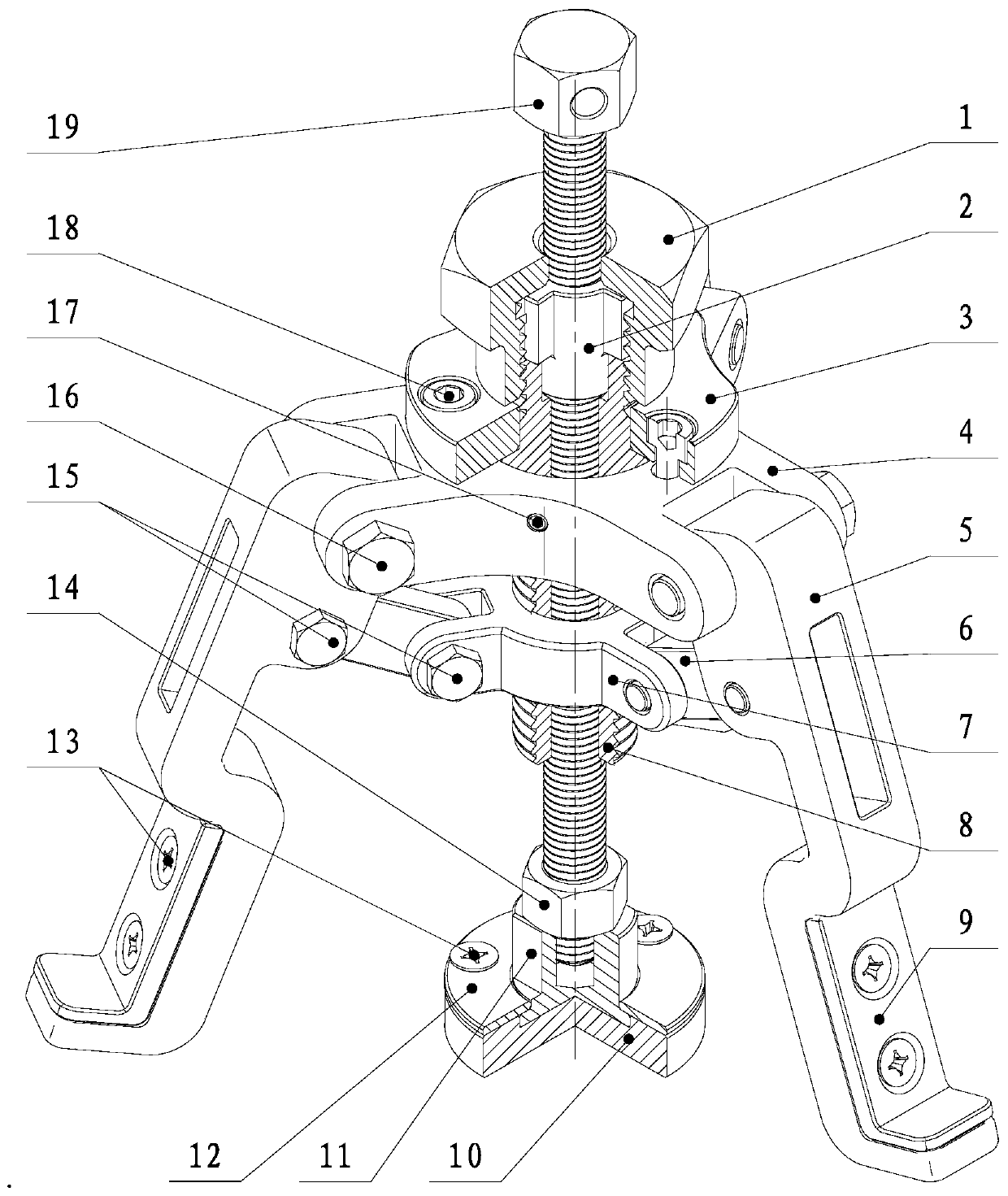
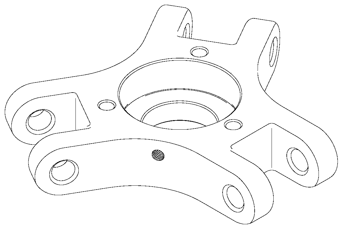
[0024] Below in conjunction with accompanying drawing, the present invention is described in further detail: 1 pressing cap, 2 wire sleeves, 3 pressing plates, 4 support blocks, 5 claws, 6 connecting rods, 7 movable blocks, 8 movable threaded rod sleeves, 9 claw stickers, 10 Force plate, 11 pressure head, 12 cover plate, 13M5 cross slotted screw, 14M16 lock nut, 15M6 limit screw, 16M8 limit screw, 17M4 lock screw, 18M6 inner hexagon screw, 19 ejector rod.

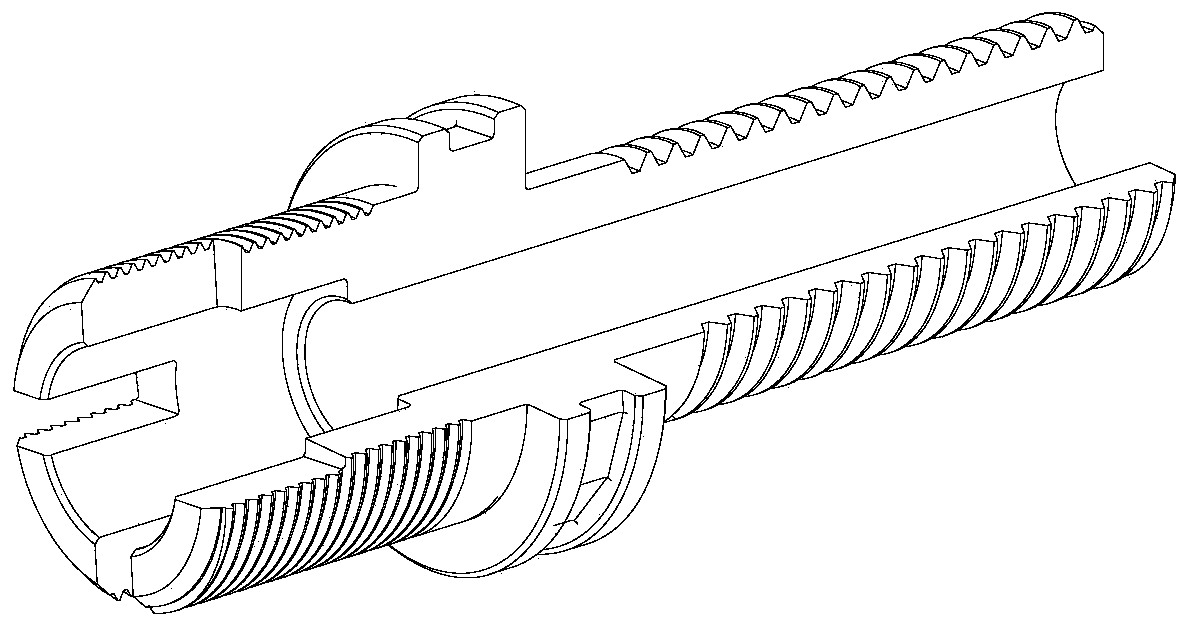
[0025] Such as figure 1 As shown, the tooling of the present invention includes a lifting adjustment element and a linkage tensioning element. Described pulling element comprises support block 4 (see figure 2 ), activity block 7 (see Figure 7 ), claw 5 (see Figure 4 ), dial and post 9 (see Figure 4 ), connecting rod 6, pressure plate 3, M8 limit screw 16, M6 limit screw 15, M6 inner hexagon screw 18, M5 cross slotted screw 13, M4 locking screw 17; the center position of support block 4 is provided with a step hole, ...


PUM


Abstract

The invention provides a puller for a rotor assembly assembling of an aero-engine. The puller comprises a supporting pulling element and a tight pressing element; the supporting pulling element comprises a supporting block, a movable block, a pulling claw, a pulling and rotating paster, a connecting rod, a pressing plate and pin shafts, wherein a step hole is formed in the center of the upper plane of the supporting block, joint holes which protrude in the circumferential direction and are uniformly distributed are formed in the side surfaces of the supporting block, holes formed in the jointholes of the supporting block and the upper end of the pulling claw are movably connected by the pin shafts or the connecting rod; the upper end part and the lower part of the pulling claw are provided with the two shaft holes, and the two shaft holes are parallel to each other; the movable block is located at the coaxial lower part of the supporting block and the upper surface of the movable block is parallel to the upper surface of the supporting block, a left-hand threaded hole is formed in the center of the upper surface of the movable block, joint holes which are uniformly distributed inthe circumferential direction at the same angle as the supporting block are also formed in the side face of the movable block, and the holes formed in the joint holes of the movable block and the lower part of the end part of the pulling claw are movably connected by the pin shafts or the connecting rod, wherein the joint holes of the movable block are parallel to the joint holes of the supportingblock; and a pressing rod fixed to a movable threaded rod sleeve is arranged in the center of the movable threaded rod sleeve, and a stress disc is fixed at the lower end of the pressing rod.

Description

technical field [0001] The invention relates to a tooling used for disassembly and use of an aeroengine rotor assembly and disc assemblies such as integral blisks and turbine disks during assembly. Background technique [0002] The rotor assembly has very high assembly requirements during the assembly process, especially the circular runout and surface runout of the assembly after the assembly is completed. It is difficult to meet the requirements of the assembly technical documents for one-time assembly. It is possible to assemble and disassemble the discs and blisks of the same level many times before they can meet the requirements of the assembly technical documents. Since the spigot fit between the disks of most rotor assemblies at all levels is an interference fit, and the interference is large, it takes time and effort during the disassembly process, and there are risks such as bumping and falling off, which will cause parts or components damage, which greatly reduces...

Claims


Application Information

Patent Timeline
Patent Type & Authority Applications(China)
IPC IPC(8): B25B27/02
CPCB25B27/023
Inventor 王永清窦爱国张宁宋学东王思慧
Owner 无锡市润和机械有限公司
Features
  • R&D
  • Intellectual Property
  • Life Sciences
  • Materials
  • Tech Scout
  • Unparalleled Data Quality
  • Higher Quality Content
  • 60% Fewer Hallucinations
Learn More