
New energy vehicle AC charging pile cluster and power control method based on cloud platform

A technology of AC charging piles and new energy vehicles, which is applied in the direction of electric vehicle charging technology, charging stations, electric vehicles, etc., can solve the problems of resource waste of power distribution facilities, related investment and difficulty, side effects of new energy vehicles, etc., to achieve Save operating costs, ensure electricity safety, and reduce operating costs

Active Publication Date: 2019-10-18
一能充电科技(深圳)股份有限公司
View PDF5 Cites 4 Cited by
  • Summary
  • Abstract
  • Description
  • Claims
  • Application Information

AI Technical Summary

Problems solved by technology

The charging standard of AC charging piles is constant power output, and the charging power of existing AC charging piles is generally 7KW; if there are 200 or more cars using charging piles at the same time, the instantaneous charging power demand may reach 1400KW, while the general property distribution There will not be so much free power margin, and when there is a simultaneous charging demand, it will inevitably cause power outages or more serious accidents for other power facilities and residents in the property
However, to meet this charging demand, not only the relevant investment and difficulty are large, but also there is a huge energy demand in a certain period of time, and some periods may be very idle, resulting in the waste of resources in power distribution facilities.
Therefore, at the current stage, there will be more and more contradictions between the fact that new energy vehicles mainly install their own charging piles in the place of residence and property electricity is not allowed to be connected, because there is no unified solution, which will bring certain difficulties to the popularization of new energy vehicles. Side effects bring many concerns to users who want to buy new energy vehicles

Method used


Image

  • New energy vehicle AC charging pile cluster and power control method based on cloud platform

Examples


Embodiment Construction

[0024] Embodiments of the present invention will be described in further detail below in conjunction with the accompanying drawings.

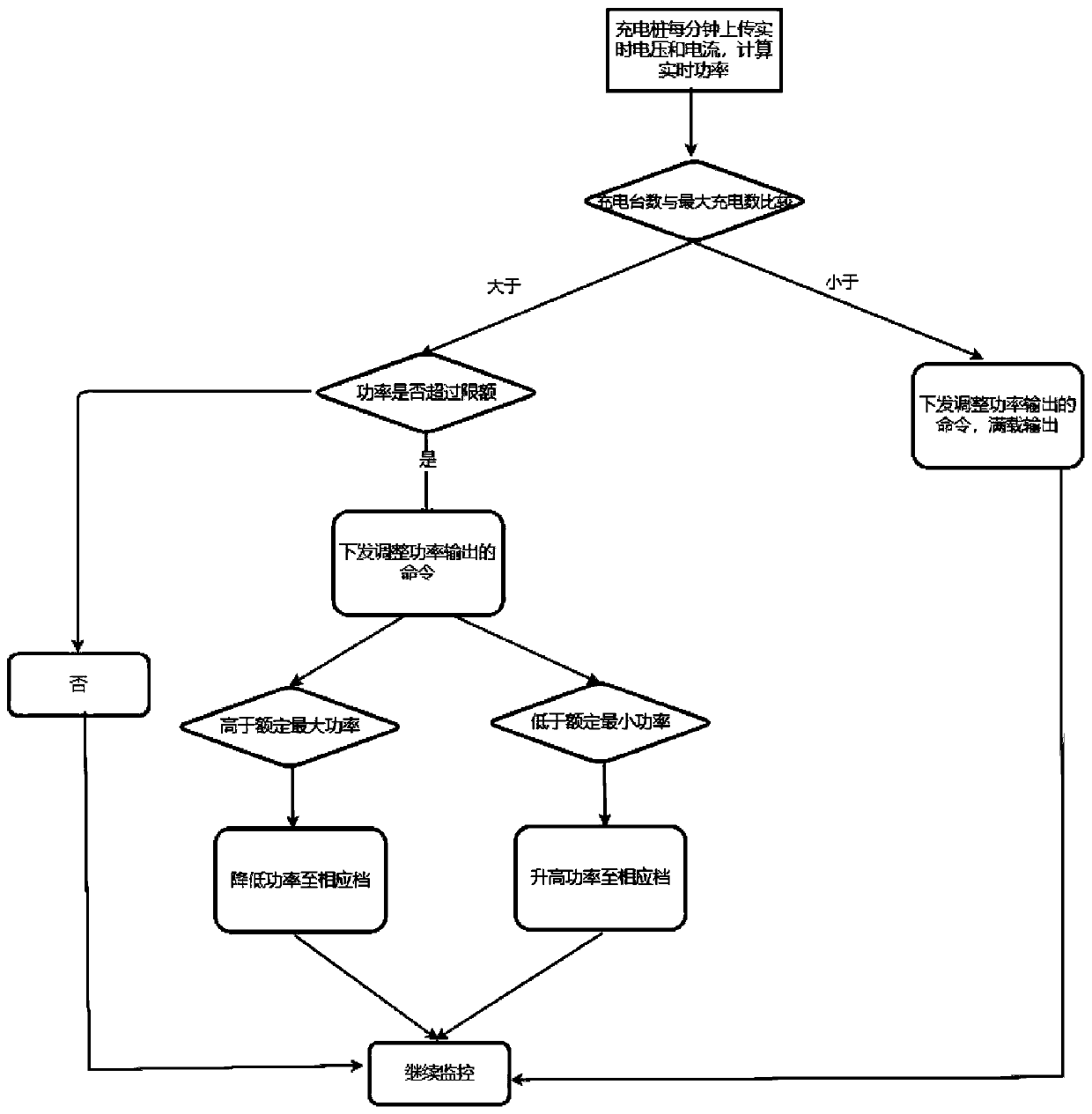
[0025] like figure 1 As shown, it is a flow chart of the power control method of the AC charging pile cluster of the present invention.

[0026] A new energy vehicle AC charging pile cluster power control method based on a cloud platform, comprising the following steps:

[0027] 1) The cloud platform sets the total power threshold of the charging pile cluster, and sets the rated maximum power and rated minimum power of the charging cluster;

[0028] 2) The cloud platform obtains the current charging voltage and current information uploaded by each charging pile in use in the charging cluster in real time;

[0029] 3) The cloud platform performs total power accumulation, and sends power adjustment instructions to each charging pile according to the accumulated real-time total power being charged:

[0030] If the number of charging piles in us...


PUM


Abstract

The invention provides a new energy vehicle AC charging pile cluster and a power control method based on a cloud platform. According to the invention, the charging power of the charging pile cluster can be regulated by a cloud server according to the total power distribution allowance of the current use place. The power control method of the present invention comprises the following steps: 1) a cloud platform sets the total power threshold of the charging pile cluster and sets a rated maximum power and a rated minimum power of the charging cluster; 2) the cloud platform obtains the current charging voltage and current information uploaded by each charging pile in use in the charging cluster in real time; 3) the cloud platform performs total power accumulation, and sends power adjustment instructions to each charging pile according to the accumulated real-time total power of the charging; and 4) the charging piles receive the power adjustment commands from the cloud platform, adjust thePWM duty cycle according to the set gear position, and upload the adjusted real-time charging data after the adjustment.

Description

technical field [0001] The invention relates to the technical field of charging management of new energy vehicles, in particular to a cloud platform-based AC charging pile cluster and power control method for new energy vehicles. Background technique [0002] At present, in order to strengthen the control of air pollution and reduce energy consumption, and implement the urban low-carbon development strategy, the development of the electric vehicle industry has become an important direction of the national new energy strategy. The construction of sound charging facilities is the premise of realizing the industrialization of electric vehicles. Charging The construction of facilities and the development of electric vehicles complement each other and promote each other. With the increasing number of new energy electric vehicles, electric vehicle charging piles are facing a demand for rapid popularization. Charging piles are divided into two forms: DC fast charging and AC slow c...

Claims


Application Information

Patent Timeline
Patent Type & Authority Applications(China)
IPC IPC(8): B60L53/31B60L53/62B60L53/68
CPCB60L53/31B60L53/62B60L53/68Y02T90/16Y02T90/167Y02T10/70Y02T10/7072Y02T90/12Y04S30/12
Inventor 周锡忠傅希全
Owner 一能充电科技(深圳)股份有限公司
Learn More