Method and hole reaming device for one-time pile forming of pile body and pile cap

A one-time, pile cap technology, used in drilling equipment and methods, sheet pile walls, earthwork drilling, etc., can solve the problems of reduced local bearing capacity, low efficiency, and puncture of foundation mattresses, and improve the bearing capacity of foundations. The effect of strength, integrity and good quality, easy installation and disassembly

Pending Publication Date: 2019-10-18
武汉谦诚桩工科技股份有限公司 +1
View PDF0 Cites 2 Cited by
  • Summary
  • Abstract
  • Description
  • Claims
  • Application Information

AI Technical Summary

Problems solved by technology

The foundations of buildings such as high-rise buildings, bridges and industrial plants generally adopt conventional bored concrete piles, PHC piles, CFG piles, etc., generally adopt the form of independent single pile and single column, or combine multiple piles through bearings. platform regeneration into load-bearing columns; while in foundation reinforcement projects with vertical bearing capacity as the main and horizontal shear force as the supplement, such as road composite foundation reinforcement treatment for railways and highways, and in railway stations, high-speed rail maintenance areas, As well as large cargo yards (containers, oil depots), etc., it is necessary to strengthen the foundation of a large range. In the past, this kind of foundation treatment generally adopts the method of pile groups, and the single pile body in the pile group is generally a cylinder. Due to the limitation of the body area, the top of the pile will often puncture the foundation cushion, resulting in a reduction in local bearing capacity or uneven settlement
In addition, CFG piles that have been widely used in the application process of composite foundation often need to carry out cumbersome procedures such as excavating pile heads, cutting piles, and supporting formwork after the completion of the concrete age. Installing "pile caps", the main process cannot be mechanized, resulting in long construction period, low efficiency, high cost and poor effect

Method used


Image

  • Method and hole reaming device for one-time pile forming of pile body and pile cap
  • Method and hole reaming device for one-time pile forming of pile body and pile cap
  • Method and hole reaming device for one-time pile forming of pile body and pile cap

Examples


Embodiment Construction

[0019] The technical solution of the present invention will be further described below in conjunction with the accompanying drawings.

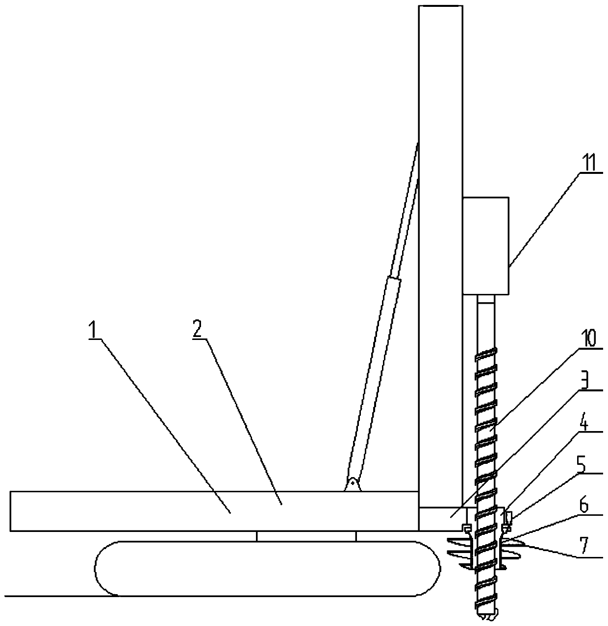
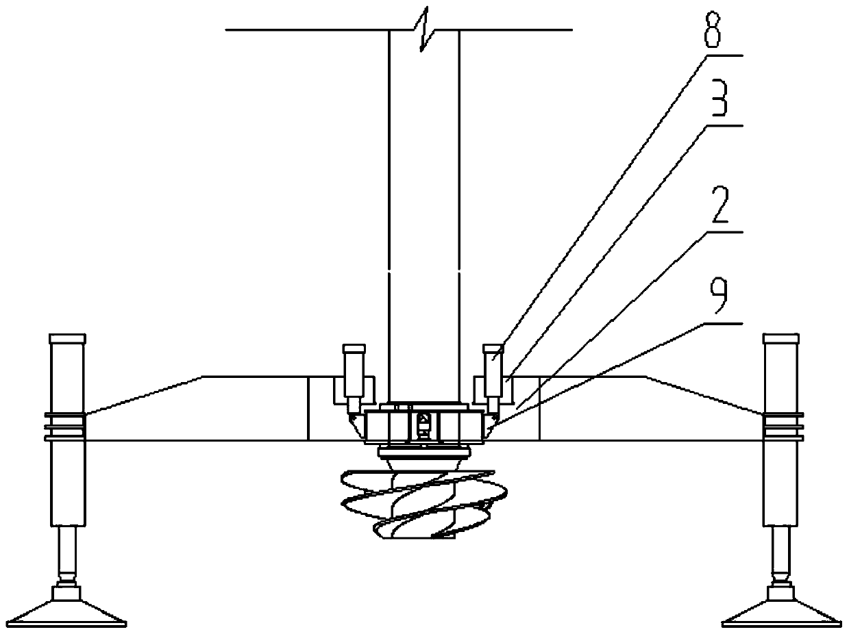
[0020] Such as figure 1 , figure 2 and Figure 4 As shown, a kind of pile body and pile cap of the present invention one-time pile reaming device comprises pile driver 1, pile driver girder 2, connecting seat 3, rotary box 4, hydraulic motor 5, slewing bearing 6, reaming Drill bit 7, pressurized oil cylinder 8, hinge plate 9, drilling rod 10, power head 11, reaming drill bit 7 are hollow, promptly its inside is cavity. The pile driver girder 2 is set on the pile driver 1, and the two connecting seats 3 are respectively connected with the pile driver girder 2 by flange bolts, the connecting seat 3 is provided with a pressurized oil cylinder 8, and the two connecting seats 3 can be respectively provided with a pressurized oil cylinder 8. There are hinged plates 9 welded on both sides of the rotary box 4, and the pressurized oil cylinder 8 an...


PUM


Abstract

The invention relates to the field of foundation treatment pile machinery in the construction industry, and relates to a method and a hole reaming device for one-time pile forming of a pile body and apile cap. The inside of a hole seaming drill bit is a cavity. A connecting seat is connected to a pile machine beam. The connecting seat is provided with a pressurized oil cylinder. The two side of arotary box are fixedly connected to hinge plates. The pressurized oil cylinder is connected to the hinge plates. The side surface of the rotary box is provided with a hydraulic motor. The lower end of the rotary box is provided with a slewing bearing. The slewing bearing is connected to the hole seaming drill bit. The hole seaming drill bit and a drill rod are coaxial. The drill rod passes through the cavity of the hole seaming drill bit. The drill rod is threaded. The drill rod is connected to a power head. The threaded pile body and the pile cap constructed by the device of the invention are seamlessly connected, and the integrity is better.

Description

technical field [0001] The invention relates to the field of foundation treatment pile machinery in the construction industry, and relates to a method for forming a pile with a pile body and a pile cap at one time and a hole reaming device thereof. Background technique [0002] With the rapid development of the country's industrial and civil construction fields, the requirements for building foundations are getting higher and higher, especially for various types of pile foundations that are widely used. The foundations of buildings such as high-rise buildings, bridges and industrial plants generally adopt conventional bored concrete piles, PHC piles, CFG piles, etc., generally adopt the form of independent single pile and single column, or combine multiple piles through bearings. platform regeneration into load-bearing columns; while in foundation reinforcement projects with vertical bearing capacity as the main and horizontal shear force as the supplement, such as road comp...

Claims


Application Information

Patent Timeline
IPC IPC(8): E02D5/36E02D15/04E21B7/28E21B10/26E21B17/22
CPCE02D5/36E02D15/04E21B7/28E21B10/26E21B17/22
Inventor 郭克诚王相民张龙姚敏孙伟
Owner 武汉谦诚桩工科技股份有限公司
Why Eureka
Try Eureka