System and method for reducing emission of flashed gas in liquefied natural gas filling process

A technology of liquefied natural gas and flash gas, which is applied in the field of pressure transportation, can solve problems such as waste safety and hidden dangers, and achieve the effect of reducing waste and emission loss

Inactive Publication Date: 2019-10-18
青岛乐戈新能源科技有限公司
View PDF6 Cites 2 Cited by
  • Summary
  • Abstract
  • Description
  • Claims
  • Application Information

AI Technical Summary

Problems solved by technology

[0005] For this reason, the embodiments of the present invention provide a system and method for reducing flash gas discharge during LNG filling, so as to solve the problems of waste and potential safety hazards caused by the treatment of flash gas in LNG storage tanks in the prior art

Method used


Image

  • System and method for reducing emission of flashed gas in liquefied natural gas filling process
  • System and method for reducing emission of flashed gas in liquefied natural gas filling process

Examples


Embodiment 1

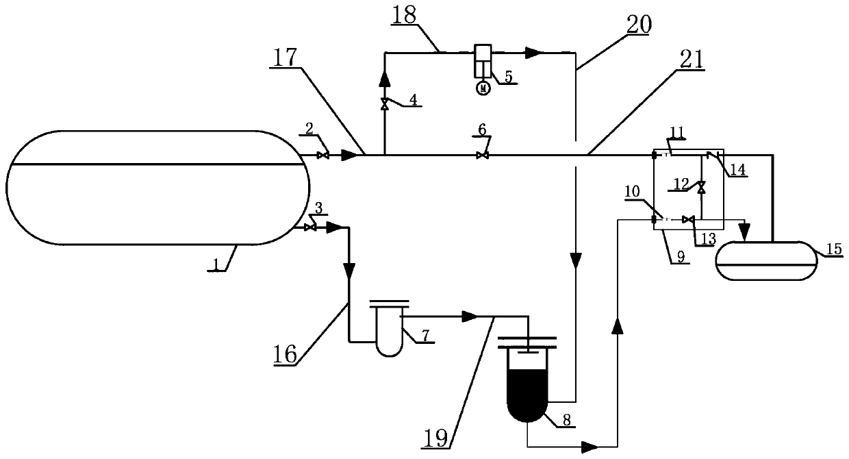
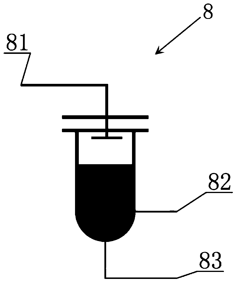
[0038] Such as Figure 1-2 Shown is a system for reducing flash gas emissions during liquefied natural gas filling. The system includes a storage tank 1, a submersible pump 7, a mixing tank 8, a compressor skid 5 and a fuel tank 15. The mixing tank 8 is A liquid phase inlet 81, a gas phase inlet 82 and a liquid phase outlet 83 are provided, the storage tank 1 communicates with the inlet of the submersible pump 7 through the first pipeline 16, and the storage tank 1 passes through the second pipeline 17 and the third pipeline 18 in turn Connected with the inlet of the compressor skid 5, the outlet of the submersible pump 7 communicates with the liquid phase inlet 81 of the mixing tank 8 through the fourth pipeline 19, and the outlet of the compressor skid 5 communicates with the liquid phase inlet 81 of the mixing tank 8 through the fifth pipeline 20. The gas phase inlet 82 of the mixing tank 8 is communicated, and the liquid phase outlet 83 of the mixing tank 8 is respectively...

Embodiment 2

[0049] A method for reducing flash gas discharge during filling of liquefied natural gas, said method uses the system described in embodiment 1; said method comprises the following steps:

[0050] a. Pre-cool the system before filling the fuel tank

[0051] The submersible pump 7 is pre-cooled first, and after the pre-cooling of the submersible pump 7 is completed, the submersible pump 7 is started, and the liquefied natural gas enters the submersible pump 7 from the storage tank 1 through the first pipeline 16, and then pressurized by the submersible pump 7 Afterwards, it is sent into the mixing tank 8 through the liquid phase inlet 81 of the mixing tank 8, and then enters the liquid feeder 9 through the liquid phase outlet 83 of the mixing tank 8, and the liquefied natural gas that enters the liquid feeder 9 passes through the liquid of the liquid feeder 9. The phase flow meter 10, the first valve 13, the second valve 12 and the gas phase flow meter 11 return to the storage ...

Embodiment 3

[0056] A method for reducing flash gas emission during filling of liquefied gas with a temperature of -273 to -20°C, wherein the liquefied gas with a temperature of -273 to -20°C is liquid nitrogen; the method comprises the following steps:

[0057] a. Pre-cool the system before filling the fuel tank

[0058] First pre-cool the submersible pump 7, after the pre-cooling of the submersible pump 7, start the submersible pump 7, liquid nitrogen enters the submersible pump 7 from the storage tank 1 through the first pipeline 16, and then pressurizes through the submersible pump 7 After that, it is sent into the mixing tank 8 through the liquid phase inlet 81 of the mixing tank 8, and then enters the liquid feeder 9 through the liquid phase outlet 83 of the mixing tank 8, and the liquid nitrogen entering the liquid feeder 9 passes through the liquid nitrogen of the liquid feeder 9. The phase flow meter 10, the first valve 13, the second valve 12 and the gas phase flow meter 11 retur...


PUM


Abstract

The embodiment of the invention discloses a system and a method for reducing emission of flashed gas in a liquefied natural gas filling process and relates to the technical field of pressurization. The system comprises a storage tank, an immersed pump, a mixing tank, a compressor pry and a fuel tank. The method comprises the following steps: a, pre-cooling the system first before filling the fueltank with liquefied natural gas; and b, filling the fuel tank with liquefied natural gas. According to the system for reducing emission of flashed gas in the liquefied natural gas filling process andthe method thereof, the flashed gas in the storage tank in the liquefied natural gas filling process is mixed by the mixing tank and is then liquefied and filled to a user to be taken away, so that the liquefied natural gas is combusted on a user side. Therefore, diffused flashed gas is turned into wealth, so that the waste of energy source is reduced, and meanwhile, the emission loss of a naturalgas station is reduced, and therefore, contribution for energy conservation and emission reduction of the state is made.

Description

technical field [0001] Embodiments of the present invention relate to the technical field of pressure transmission, and in particular to a system and method for reducing flash gas discharge during LNG filling. Background technique [0002] At present, coal and oil are still the main energy consumption of human beings. In the primary energy consumption structure, coal accounts for 68.5%, oil accounts for 17.7%, and natural gas accounts for only 4.7%, which is far lower than the world average of 24%. This coal-based energy consumption structure will bury hidden dangers in the atmospheric environment. [0003] As the national environmental protection policy becomes more and more stringent, the clean energy liquefied natural gas (LNG) can be developed. With the use of liquefied natural gas (LNG) as a vehicle power technology, the number of LNG vehicle refueling stations in my country has developed rapidly in recent years. . LNG vehicle filling stations generally use full-pressu...

Claims


Application Information

Patent Timeline
Patent Type & Authority Applications(China)
IPC IPC(8): F17C5/02F17C13/00F17C13/02F17C13/04
CPCF17C5/02F17C13/00F17C13/02F17C13/04F17C2221/031F17C2221/032F17C2221/033F17C2223/0161F17C2227/0339F17C2265/034
Inventor 彭国干韦育强盖云杨山举刘青
Owner 青岛乐戈新能源科技有限公司
Why Eureka
Try Eureka