Hoisting erection system and erection control method for rocket launch platform at sea

A launch pad and rocket technology, which is applied in the direction of rocket launchers, offensive equipment, weapon types, etc., can solve the problem of failure to provide reverse thrust, affecting the safety of rockets and launch pads, damage to quiver assemblies or launch pads, etc. question

Active Publication Date: 2021-10-15
BEIJING INST OF SPACE LAUNCH TECH +1
View PDF0 Cites 0 Cited by
  • Summary
  • Abstract
  • Description
  • Claims
  • Application Information

AI Technical Summary

Problems solved by technology

However, for sea launch rigs, due to the limitation of the distance between the rotary axes and the space of the launch ship, the hydraulic cylinder is no longer suitable as the actuator of the erection system, and the dynamic environment at sea is relatively complex, so the hydraulic cylinder cannot be redundantly backed up, and the safety is poor
In response to this problem, the offshore launch platform usually adopts a flexible steel cable erection system, but the existing flexible steel cable erection system has the following problems in the implementation and application: because the flexible steel cable can only provide one-way tension, it cannot provide feedback. In the process of erection, when the overall center of mass of the erection frame and quiver assembly crosses the vertical plane where the rotary shaft is located, a stall phenomenon will occur, which seriously affects the safety of the rocket and the launch platform. If a mechanical limit mechanism is used to control Stall, there will be an impact between the parts that are in contact, which can also cause damage to the quiver assembly or launch stand

Method used


Image

  • Hoisting erection system and erection control method for rocket launch platform at sea
  • Hoisting erection system and erection control method for rocket launch platform at sea
  • Hoisting erection system and erection control method for rocket launch platform at sea

Examples


Embodiment Construction

[0030] First of all, it needs to be explained that the orientation words such as up, down, left, right, front, and back described in the present invention are only described according to the accompanying drawings, so as to facilitate understanding, and are not intended to limit the technical solution and scope of protection of the present invention. .

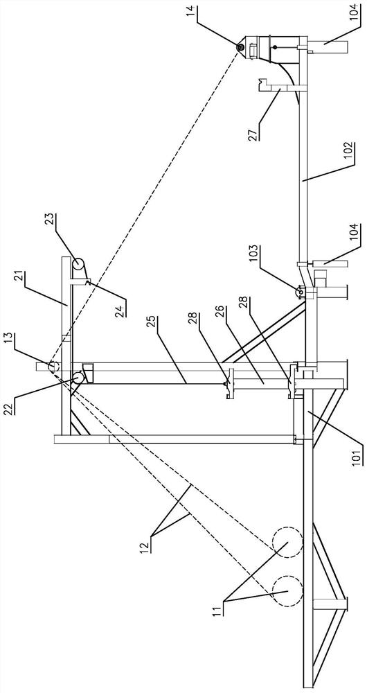
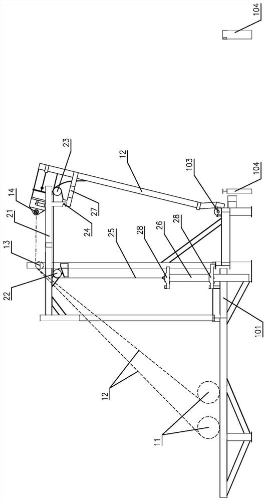
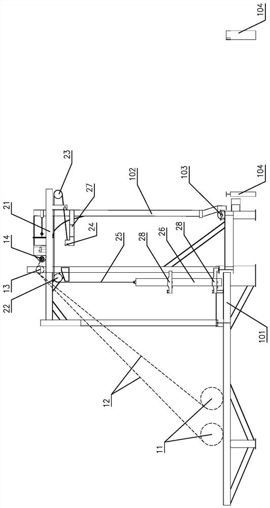
[0031] Such as Figure 1 to Figure 6 The specific implementation of the hoisting and erecting system for the rocket sea launch platform of the present invention is shown, including an erecting unit and a buffer unit. Make erecting unit to comprise hoist 11 and erect wire rope 12, hoist 11 is installed and fixed on the abutment left half of fixed frame 101, allow the left end of erect wire rope 12 to be fixedly connected with hoist 11, allow the right end of erect wire rope 12 to wind The erecting pulley 13 provided on the top of the fixed frame 101 is fixedly connected with the connecting ring 14 on the erecting frame 102 . T...


PUM


Abstract

The invention relates to a hoisting and erecting system and an erecting control method for a rocket launch platform at sea. The hoisting and erecting system includes an erecting unit and a buffer unit, and the erecting unit includes a hoist, an erecting steel wire rope, an erecting pulley and a connection Ring; the buffer unit includes a support arm, a buffer pulley, a reversing pulley, a limit rod, a buffer wire rope, a pendant and a docking arm. The support arm is fixed with two limit plates, and the left side of the two limit plates is provided with a limit card slot, the limit rod is in the limit card slot of the two limit plates, the limit rod is connected to one end of the buffer wire rope, the other end of the buffer wire rope is connected to the pendant by bypassing the reversing pulley and the buffer pulley, and the docking arm is fixed on On the erecting frame, two docking plates are fixed on the upper end of the docking arm, and the upper side of the two docking plates is provided with a docking card slot, which has the advantages of simple structure, stable movement, safety and reliability, good cushioning effect and strong adaptability. The erecting control method has the advantages of simple process, easy realization and high safety.

Description

technical field [0001] The invention relates to an erecting system, in particular to a hoisting and erecting system and an erecting control method for a rocket launch platform at sea. Background technique [0002] In the field of rocket launching, the launch platform is usually designed to be composed of a fixed frame and a vertical frame, and the two are hinged through the rotary shaft, so that the quiver assembly (the combination of the rocket and the launch tube) is hoisted and fixed on the vertical frame. on the frame, and through the erecting system, the erecting frame is rotated around the rotary axis to complete the erecting action of the rocket. For the traditional land launch platform, the actuator of the erection system usually adopts a hydraulic cylinder, because the hydraulic cylinder is a two-force rod structure, which can provide both pulling force and thrust force, and the speed can be controlled by the hydraulic damping buffer structure to achieve smoothness ...

Claims


Application Information

Patent Timeline
Patent Type & Authority Patents(China)
IPC IPC(8): F41F3/04
CPCF41F3/04
Inventor 何轩秦利姜续贾学军张云巧杨会菊赵永涛王玺何冠杰欧阳松
Owner BEIJING INST OF SPACE LAUNCH TECH
Why Eureka
Try Eureka