Anti-rotation and play-proof crimp sleeve assembly and connector using the same

A technology of crimping sleeves and connectors, which is applied in the direction of electrical components, etc., can solve the problems of poor anti-rotation and anti-movement effects of cables, reduced rigidity of the installation panel, and limited sealing of the installation hole, so as to avoid rigidity The effect of greatly weakening, simple and reliable assembly, and enhanced sealing

Active Publication Date: 2021-04-06
CHINA AVIATION OPTICAL-ELECTRICAL TECH CO LTD
View PDF7 Cites 0 Cited by
  • Summary
  • Abstract
  • Description
  • Claims
  • Application Information

AI Technical Summary

Problems solved by technology

The existing plug connectors are all directly installed on the installation panel of the equipment through the installation flange and bolts and other fixing parts. This fixing method needs to open at least four fixing holes on the installation panel, plus a hole for the cable to pass through. If there are too many large-diameter holes, it will lead to too many holes in a small area, resulting in a significant reduction in the rigidity of the mounting panel; and because radial seals such as sealing rings are located in the plug connector outside the mounting panel , the sealing of the installation hole is limited. For example, in the long-term vibrating working environment, the bolts may be loose and the installation flange may be loose. If the maintenance is not timely, it will lead to dust, water, etc.
In addition, the existing plug connector housing is an insulating housing, which can only achieve single-channel shielding conduction, and cannot ensure reliable shielding contact; moreover, the anti-rotation and anti-movement effects on cables are not good

Method used


Image

  • Anti-rotation and play-proof crimp sleeve assembly and connector using the same
  • Anti-rotation and play-proof crimp sleeve assembly and connector using the same
  • Anti-rotation and play-proof crimp sleeve assembly and connector using the same

Examples


Embodiment Construction

[0030] The technical solutions of the present invention will be further described in detail below in conjunction with the accompanying drawings and preferred embodiments.

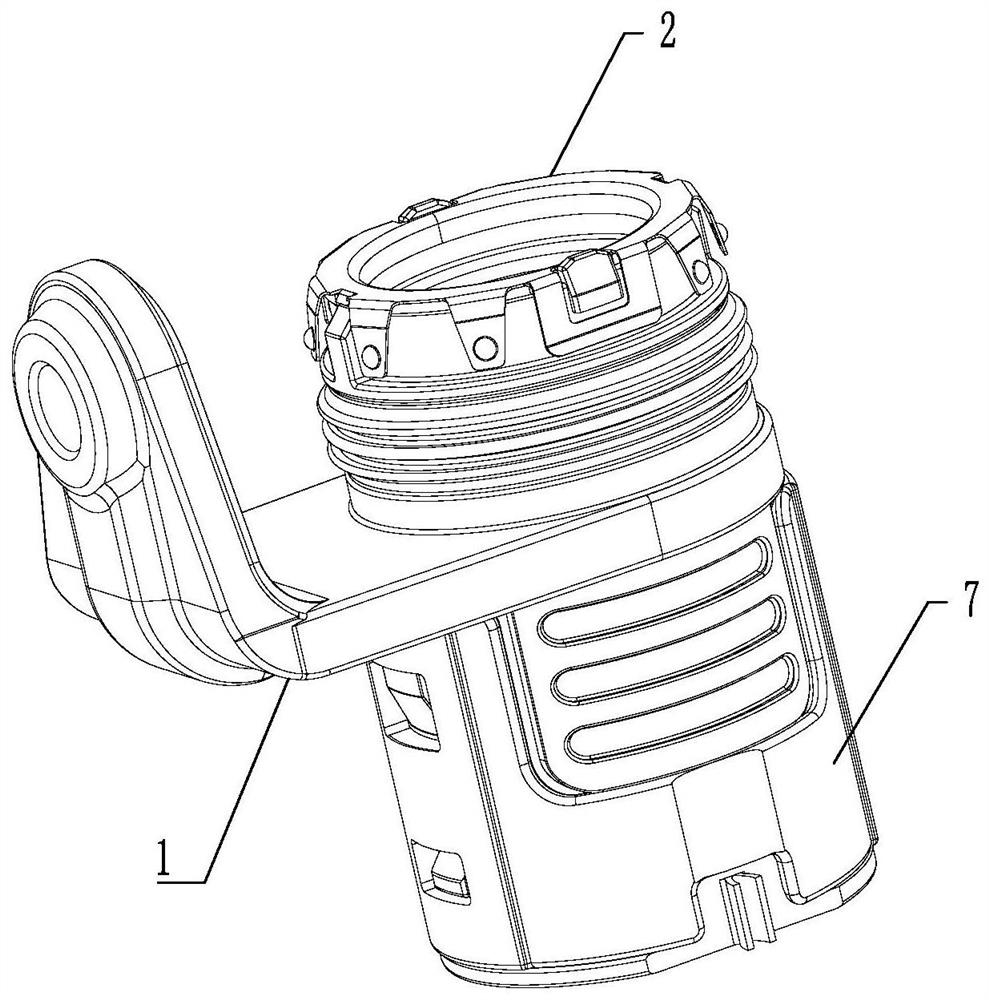
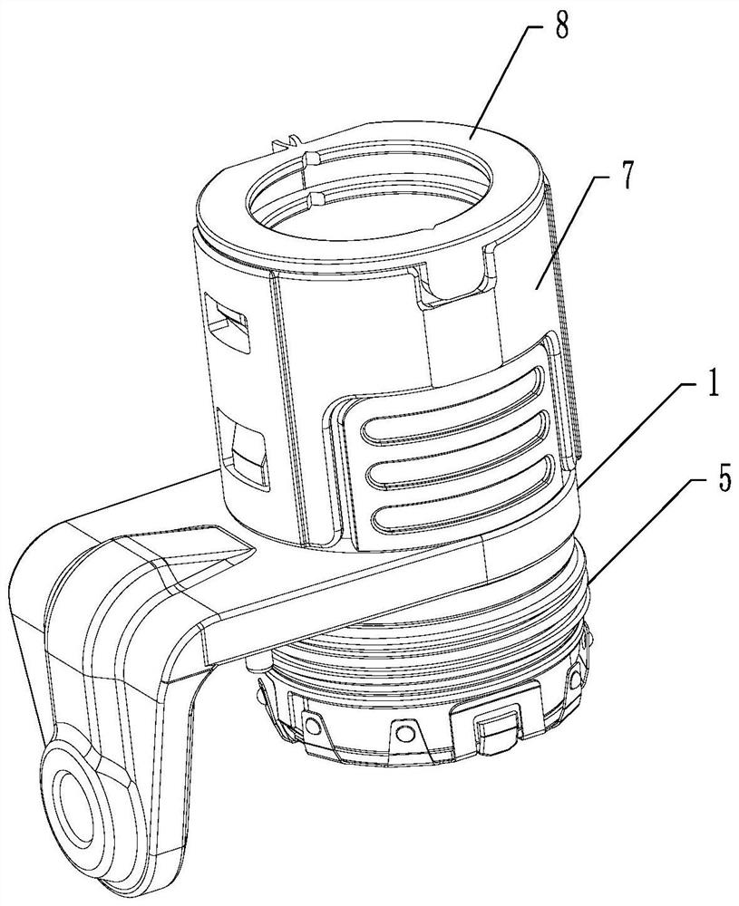
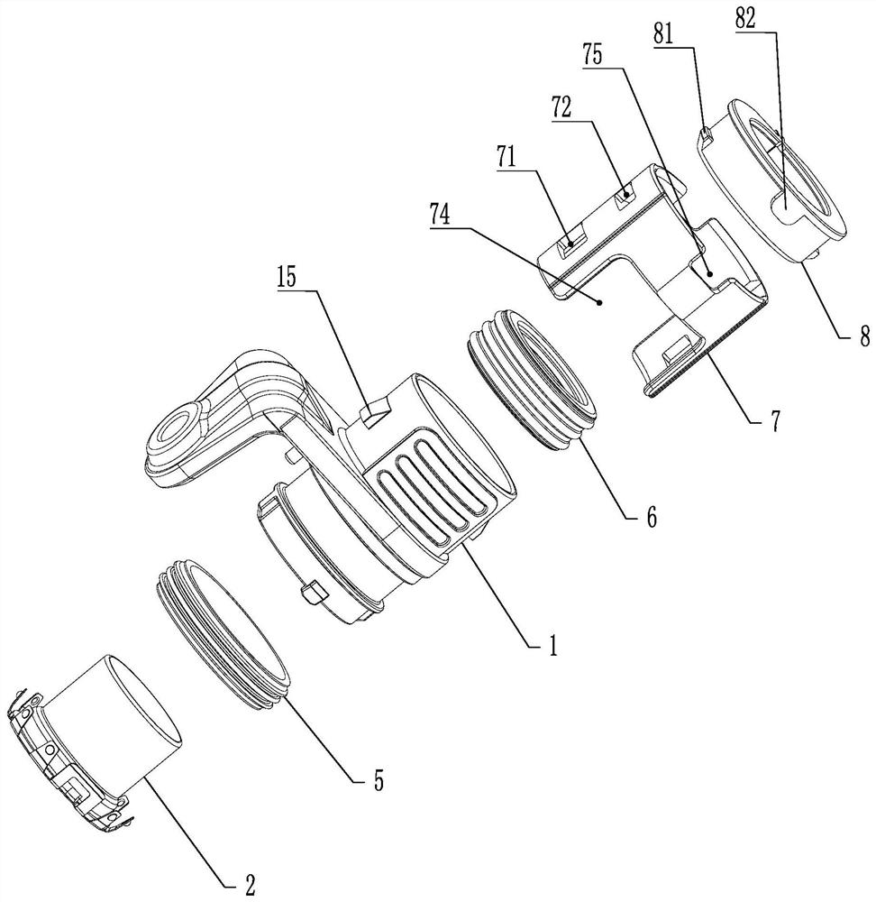
[0031] The specific embodiment of the connector proposed by the present invention, such as Figure 1 to Figure 8 As shown, it includes a metal shell 1. A threading hole perpendicular to the installation panel is opened in the metal shell 1. A crimping sleeve assembly 2 is axially installed in the threading hole. The crimping barrel 3 in contact with the cable shielding layer can ensure the pull-off force and contact reliability with the cable after crimping; the front end of the crimping barrel 3 is welded with a shrapnel 4 through spot welding, and the end face 41 That is, the end face perpendicular to the axis of the crimping barrel) is folded toward the rear end of the crimping barrel 3 so as to form a plurality of elastic arms 42 that elastically press against the inner wall of the straight hole on the ...


PUM


Abstract

The invention provides a crimping sleeve assembly that prevents rotation and movement and a connector using the crimping sleeve assembly. The connector includes a metal shell, and a threading hole is opened in the metal shell, and a crimping socket is installed in the threading hole. The sleeve assembly, the crimping sleeve assembly includes a crimping barrel, and the front end of the crimping barrel is welded with a shrapnel, and the end of the shrapnel is folded toward the rear end of the crimping barrel to form an elastic pressure against the inner wall of the straight hole on the installation panel during use. Elastic arm, the turning angle of the elastic arm is less than 90°; the valgus edge provided at the front end of the crimping barrel is provided with a positioning keyway and an anti-rotation keyway, and the elastic piece is provided with a positioning key and a direction toward the rear end of the crimping barrel. For the bent elastic hook, the front end of the metal shell is provided with an anti-rotation key matched with the anti-rotation key groove, and the anti-rotation key is buckled connected with the elastic hook. The connector of the present invention has better anti-rotation and movement functions, and is suitable for installation in holes or other special occasions. It not only reduces the opening of equipment, but also realizes the dual-channel shielding conduction effect.

Description

technical field [0001] The invention belongs to the field of plug connector equipment, in particular to a crimping sleeve assembly which prevents rotation and movement and a connector using the crimping sleeve assembly. Background technique [0002] The plug connector is used to seal and fix the cable when connecting the cable to the inside of the device, and in special environments, it is necessary to shield the electric field generated by the cable. The existing plug connectors are all directly installed on the installation panel of the equipment through the installation flange and bolts and other fixing parts. This fixing method needs to open at least four fixing holes on the installation panel, plus a hole for the cable to pass through. If there are too many large-diameter holes, it will lead to too many holes in a small area, resulting in a significant reduction in the rigidity of the mounting panel; and because radial seals such as sealing rings are located in the plug...

Claims


Application Information

Patent Timeline
Patent Type & Authority Patents(China)
IPC IPC(8): H02G3/06
CPCH02G3/0666
Inventor 娄鹏
Owner CHINA AVIATION OPTICAL-ELECTRICAL TECH CO LTD
Why Eureka
Try Eureka