
Welding equipment for rapid cooling and quenching of atomized water

A technology for rapid cooling and welding equipment, applied in quenching devices, heat treatment equipment, manufacturing tools, etc., can solve the problems of cumbersome replacement or cleaning of filter devices, waste of water resources, excessive volume, etc., to achieve convenient replacement or cleaning operations, The effect of small footprint and small volume

Inactive Publication Date: 2019-10-22
岳福连
View PDF0 Cites 0 Cited by
  • Summary
  • Abstract
  • Description
  • Claims
  • Application Information

AI Technical Summary

Problems solved by technology

[0003] 1. Quenching can enhance the strength and hardness of steel and cast iron. The rate of rapid cooling will also affect the surface hardness and core hardness of the material. After quenching, the material will become brittle, so tempering is usually performed to reduce the brittleness of the material. temperature, but the general quenching is to directly fill a container with cold water, but in the existing quenching process, the gas quenching is too slow and the water quenching is too fast;
[0004] 2. The impurity water in the quenching process is generally discarded directly after multiple uses, or reused multiple times. In order to avoid the rapid rise of the water temperature, it generally takes up a large area for storage, which is too large and difficult to operate, and causes waste of water resources;
[0005] 3. The water after quenching needs to be further filtered before it can be further used. However, the filter device on the general equipment is fixedly installed in the equipment, and the replacement or cleaning of the filter device is extremely cumbersome.

Method used


Image

  • Welding equipment for rapid cooling and quenching of atomized water
  • Welding equipment for rapid cooling and quenching of atomized water
  • Welding equipment for rapid cooling and quenching of atomized water

Examples


Embodiment Construction

[0024] The following will clearly and completely describe the technical solutions in the embodiments of the present invention with reference to the accompanying drawings in the embodiments of the present invention. Obviously, the described embodiments are only some, not all, embodiments of the present invention. Based on the embodiments of the present invention, all other embodiments obtained by persons of ordinary skill in the art without making creative efforts belong to the protection scope of the present invention.

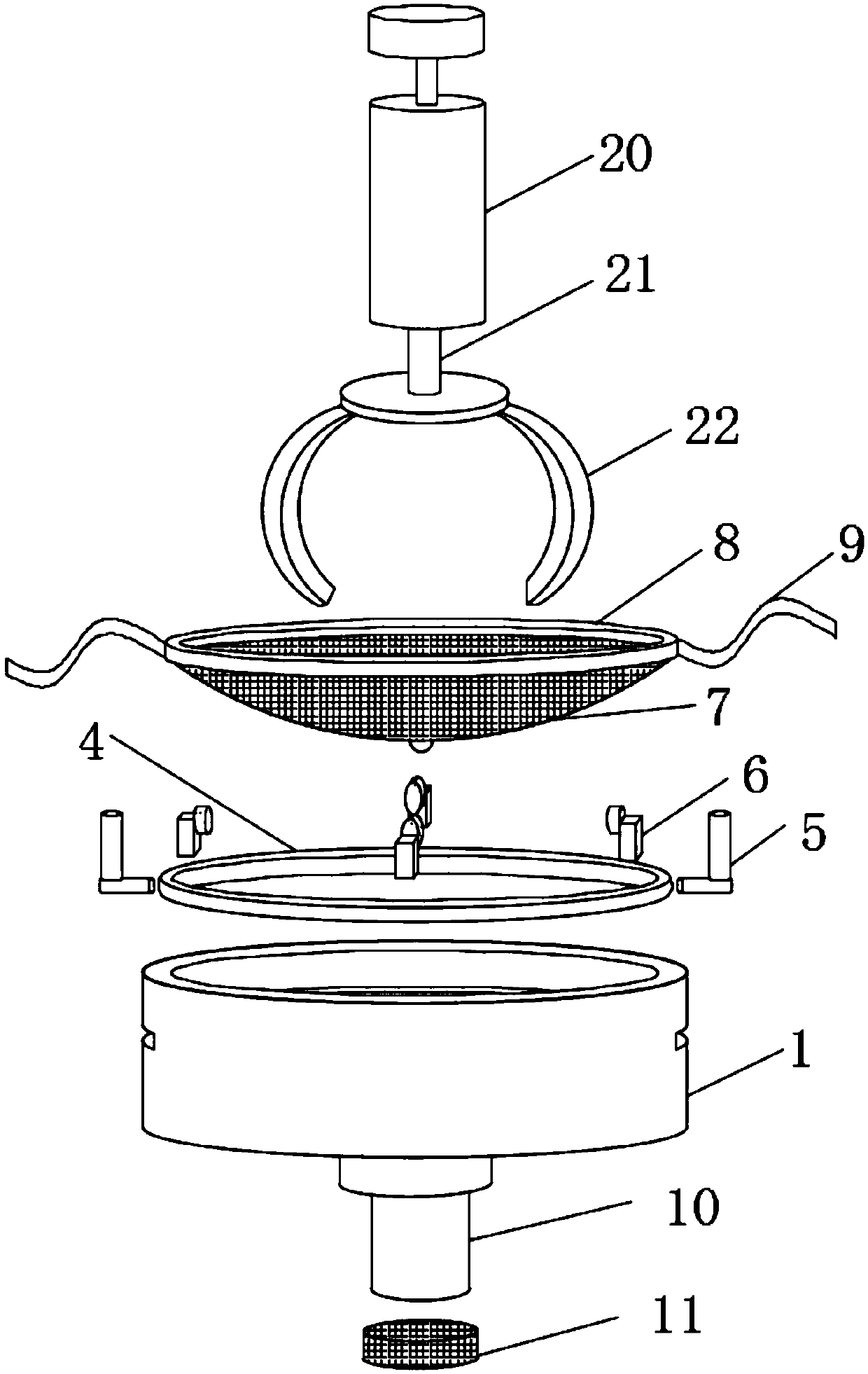
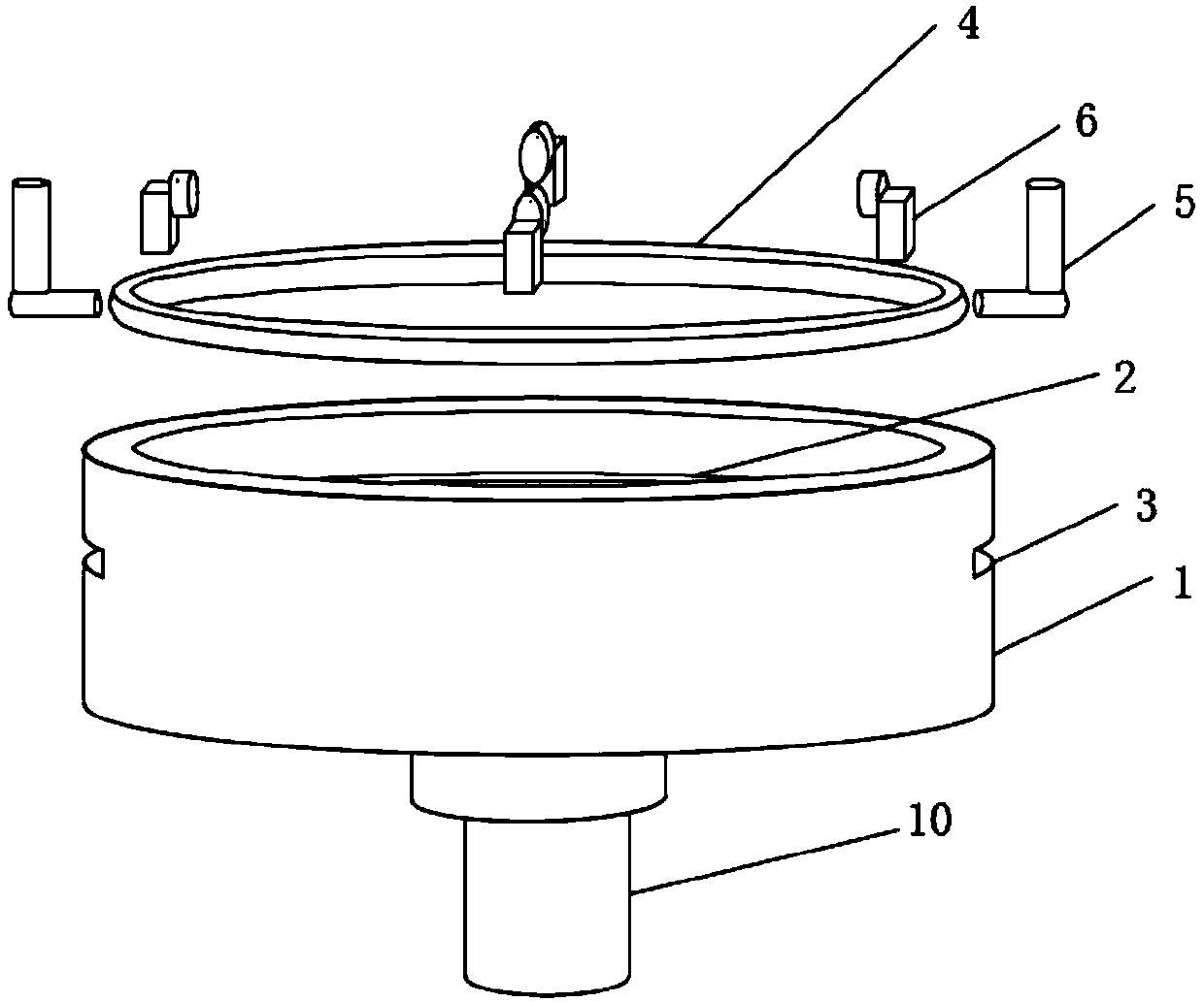
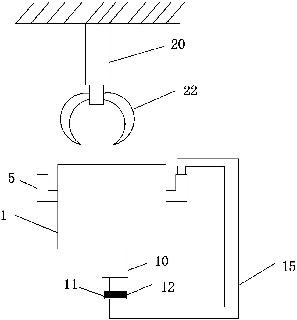
[0025] see Figure 1 to Figure 5 , the present invention provides a technical solution: a welding equipment for rapid cooling and quenching of atomized water, comprising a quenching tank 1, an installation groove 2 is arranged in the quenching tank 1, a transition pipe 4 is fixedly connected in the installation groove 2, and the quenching The tank 1 is provided with a through groove 3, the water supply pipe 5 is fixedly connected to the through groove 3, the a...


PUM


Abstract

The invention discloses welding equipment for rapid cooling and quenching of atomized water. The welding equipment comprises a quenching tank, a mounting groove is formed in the quenching tank, a transition tube is fixedly connected with the interior of the mounting groove, and a through groove runs through the quenching tank. A water adding pipe is fixedly connected with the interior of the through groove, and an atomizing nozzle is fixedly connected to the transition tube. Compared with traditional gas quenching and water quenching, by means of atomized quenching, the quenching speed can bebetter controlled, so that defects of the surface of a quenched workpiece are fewer, the workpiece is more complete, and the product quality is improved. The quenching tank is arranged below an atomizing and quenching device, water resources can be repeatedly utilized, and a conservation effect is achieved. Compared with a traditional water storage tank, the occupied area is smaller, and the sizeis smaller. By means of multiple filtering devices, impurities of the repeatedly used water can greatly reduced. The filtering devices of the equipment are all convenient to dismount and mount, and the filtering devices can be conveniently replaced or cleaned.

Description

technical field [0001] The invention relates to the technical field of mechanical equipment, in particular to welding equipment for rapid cooling and quenching with atomized water. Background technique [0002] Quenching, commonly known as dipping fire, is a heat treatment process for metal and glass. Heating the alloy product or glass to a certain temperature, and then rapidly cooling it in water, oil or air containing minerals, generally used to improve the hardness and strength of the alloy, so as to achieve the purpose of easy operation, but it still exists in actual use The following disadvantages: [0003] 1. Quenching can enhance the strength and hardness of steel and cast iron. The rate of rapid cooling will also affect the surface hardness and core hardness of the material. After quenching, the material will become brittle, so tempering is usually performed to reduce the brittleness of the material. temperature, but the general quenching is to directly fill a cont...

Claims


Application Information

Patent Timeline
Patent Type & Authority Applications(China)
IPC IPC(8): C21D1/667
CPCC21D1/667
Inventor 岳福连
Owner 岳福连
Learn More