An easy-to-operate needle row replacement device for a carding machine

A technology for replacing equipment and needle-carding machines. It is applied in the fields of combing machines, textile and papermaking, and fiber processing.

Active Publication Date: 2020-10-27
ZHEJIANG YILEI WOOLLEN SPINNING & WEAVING
View PDF5 Cites 0 Cited by
  • Summary
  • Abstract
  • Description
  • Claims
  • Application Information

AI Technical Summary

Problems solved by technology

During use, the comb box is easy to wear or get stuck and damaged after long-term use, and the entire comb box needs to be replaced. The replacement cost is high and the installation is difficult
[0003] In response to the above phenomenon, a needle comb machine has been developed in China, which only needs to replace the existing comb box of the comb box. However, it is difficult to install the needle row of this structure. When the needle row is installed on the needle board, the needle row The needle handle is difficult to insert into the installation groove of the needle plate, the needle row is difficult to bear force, and the needle row needs to be aligned with the needle box, which is time-consuming and laborious, and is easily damaged during the installation process, so it needs to be improved

Method used


Image

  • An easy-to-operate needle row replacement device for a carding machine
  • An easy-to-operate needle row replacement device for a carding machine
  • An easy-to-operate needle row replacement device for a carding machine

Examples


Embodiment 1

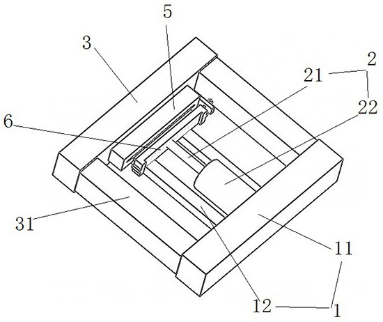
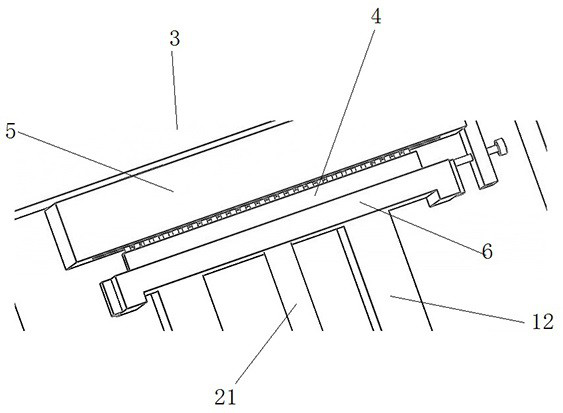
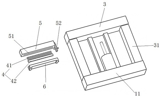
[0032] Such as Figure 1~5 As shown, an easy-to-operate needle row replacement device for a carding machine includes a frame body 1, a cylinder 2 installed on the frame body 1, a stopper located on the travel route of the piston rod 21 of the cylinder 2 and perpendicular to the travel route. Seat 3 and the fixed box 5 for accommodating the fixed needle row 4, the frame body 1 includes the mounting seat 11 arranged at the bottom end of the cylinder body 22 of the cylinder 2 and the mounting seat 11 fixed on the mounting seat 11 and located on both sides of the cylinder 2. The parallel connecting rod 12 clamped by the cylinder 2 on the side, the stopper 3 is fixedly connected with the ends of the two connecting rods 12, and the fixed box 5 is a strip-shaped metal block, the middle of which is along its length A needle groove 51 for inserting the comb needles 41 of the needle row 4 is provided in the direction, and the thickness of the needle groove 51 is smaller than the thickne...

Embodiment 2

[0042] This embodiment is based on embodiment 1, and its technical scheme is basically the same as embodiment 1, the difference is:

[0043]In this embodiment, the thickness of the fixed box 5 is greater than the thickness of the needle plate 6, and the present invention is also provided with several gaskets (not shown in the figure) with a smaller thickness, and the thickness of the gaskets is 0.5 ~ 1 mm, preferably 0.5 mm in this embodiment, by placing several pieces of the gaskets under the needle plate 6, the height of the installation groove 61 of the needle plate 6 is adjusted, which is convenient for the installation groove 61 and Alignment of needle shaft 42.

Embodiment 3

[0045] This embodiment is based on embodiment 1, and its technical scheme is basically the same as embodiment 1, the difference is:

[0046] Such as Figure 7 As shown, the bottom of the cylinder body 22 of the cylinder 2 is attached to the mounting seat 11, and a pressure sensor 71 is also arranged between the cylinder 2 and the mounting seat 11, and the pressure sensor 71 is connected to an ECU controller. 72. The ECU controller 72 is electrically connected to the cylinder 2, and the ECU controller 72 is preset with a safety pressure value. When the cylinder 2 is running and the piston rod 21 pushes the needle plate 6, the pressure sensor 71 will detect When the needle bar 6 and the needle bar 4 are gradually installed closer to the pressure value, the pressure value will gradually increase until the needle bar 4 and the needle bar 6 are installed. At this time, the cylinder 2 will continue to work. When the When the pressure value detected by the pressure sensor 71 reaches...


PUM

PropertyMeasurementUnit
thicknessaaaaaaaaaa
thicknessaaaaaaaaaa

Abstract

The invention discloses convenient-to-operate faller gill replacement equipment for a gilling machine. The equipment comprises a frame, an air cylinder, a retaining seat and a fixing box, the air cylinder is mounted on the frame, the retaining seat is positioned on a route of a piston rod of the air cylinder and perpendicular to the same, and the fixing box is used for holding and fixing a fallergill. The frame comprises a mounting seat and parallel connecting rods, the mounting seat is arranged at the bottom end of a cylinder body of the air cylinder, the connecting rods are fixed to the mounting seat and arranged on two sides of the air cylinder to clamp the air cylinder, and the retaining seat are fixedly connected with ends of the two connecting rods. The fixing box is a rectangular metal block, the middle of the fixing box is provided with a gill groove for insertion of gill pins of the faller gill, and the gill groove is thinner than a shank of the faller gill. By extrusion of the fixing box and a faller, faller gill mounting and replacement are realized, damages of the faller gill in a mounting process are avoided, and great mounting effects are achieved. By the air cylinder for pushing the faller gill, time saving and labor saving are realized.

Description

technical field [0001] The invention belongs to the technical field of textile equipment, and in particular relates to an easy-to-operate needle row replacement device for a carding machine. Background technique [0002] The needle carding machine is a machine that relies on the needle roller drafting mechanism to draft, comb, and combine the fiber strips to make the fibers straight and parallel to make fiber strips of a certain thickness. The most frequently used machine in the sliver and silk spinning process. During use, the comb box is easily worn or stuck and damaged after being used for a long time, and the entire comb box needs to be replaced, which is costly to replace and difficult to install. [0003] In response to the above phenomenon, a needle comb machine has been developed in China, which only needs to replace the existing comb box of the comb box. However, it is difficult to install the needle row of this structure. When the needle row is installed on the ne...

Claims


Application Information

Patent Timeline
Patent Type & Authority Patents(China)
IPC IPC(8): D01G19/10
CPCD01G19/10
Inventor 沈金明徐菂嵇志宏程红霞
Owner ZHEJIANG YILEI WOOLLEN SPINNING & WEAVING
Why Eureka
Try Eureka