In-place cold recycling device and method for foam asphalt
A technology of foamed asphalt and cold regeneration, which is applied in the direction of roads, road repairs, roads, etc. It can solve the problems of unfavorable road surface rapid paving, no asphalt road construction equipment, and low work efficiency, so as to improve service life, optimal structural strength, Anti-splash effect
- Summary
- Abstract
- Description
- Claims
- Application Information
AI Technical Summary
Problems solved by technology
Method used
Image

Examples
specific Embodiment approach 1
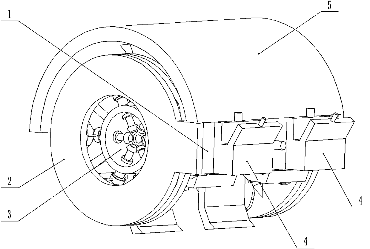
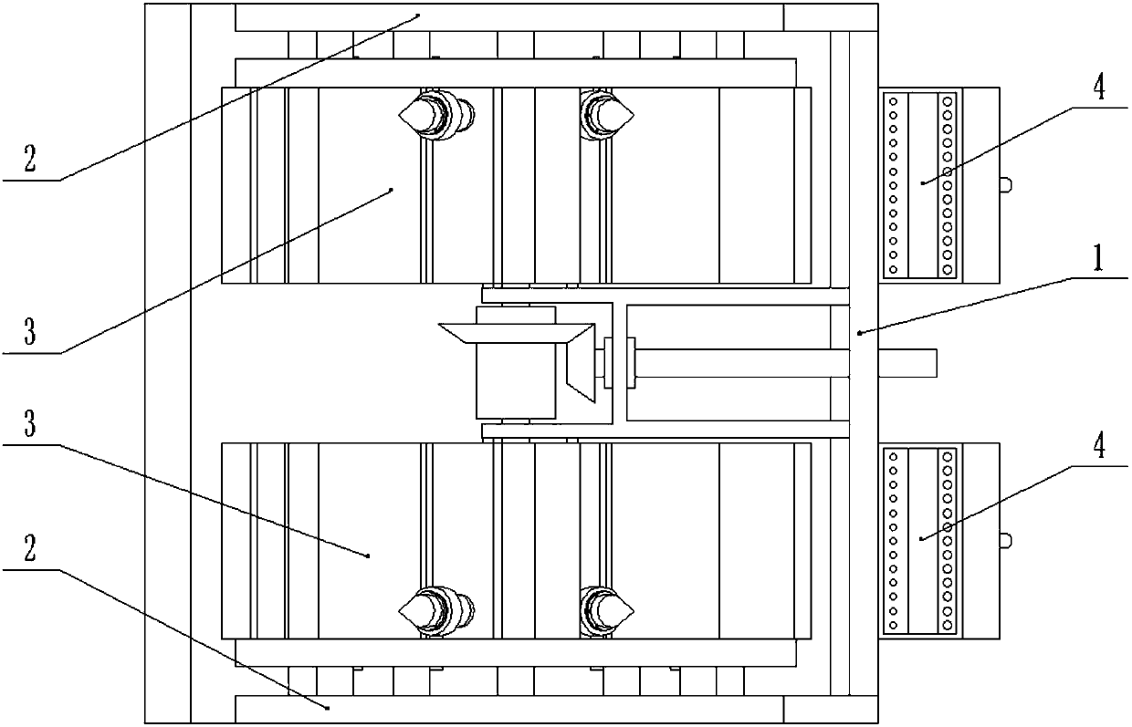
[0033] Combine below Figure 1-10 Description of this embodiment, the foamed asphalt in-situ cold recycling device includes a transmission frame 1, a drill bit sliding frame 2, a planing wheel 3, a foam box 4 and an arc-shaped baffle 5, and the two ends of the transmission frame 1 are respectively The drill bit sliding frame 2 is fixedly connected, the ground planing wheel 3 is rotatably connected to the two ends of the transmission frame 1, the ground planing wheel 3 is slidably connected to the drill bit sliding frame 2, and the foaming box 4 is fixedly connected to the transmission frame 1. On the frame 1, the arc-shaped baffle 5 is fixedly connected to the upper end of the transmission frame 1; when in use, the foamed asphalt in-situ cold regeneration device is driven by the traction vehicle to advance along the asphalt road to be regenerated, and the transmission frame 1 passes through the coupling Connect the transmission shaft of the engine on the tractor, the ground pl...
specific Embodiment approach 2
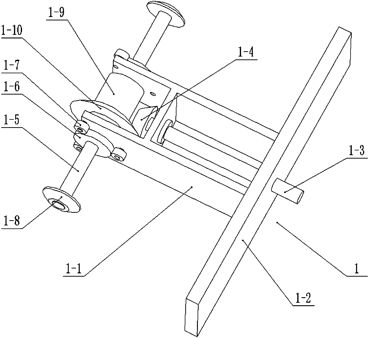
[0035] Combine below Figure 1-10Illustrate this embodiment, and this embodiment will further explain Embodiment 1. The transmission frame 1 includes an I-shaped frame 1-1, a shaft frame 1-2, a driving main shaft 1-3, a driving bevel gear 1-4, a driven Shaft 1-5, driven gear 1-6, planetary gear 1-7, transmission bevel gear 1-8, coupling 1-9 and coupling bevel gear 1-10, the shaft frame 1-2 is fixedly connected At the right end of the I-shaped frame 1-1, the drive spindle 1-3 is rotatably connected to the I-shaped frame 1-1 and the shaft frame 1-2, and the driving bevel gear 1-4 is fixedly connected to the drive spindle 1-3. The left end of the work frame 1-1 is rotatably connected with two driven shafts 1-5, and the two driven shafts 1-5 are fixedly connected by a coupling 1-9, and the driven shaft 1- 5 is fixedly connected with a driven gear 1-6, and three planetary gears 1-7 are respectively rotatably connected on the front and rear end faces of the left end of the said I-s...
specific Embodiment approach 3
[0037] Combine below Figure 1-10 Describe this embodiment mode, this embodiment mode will further explain embodiment two, described drill bit slide frame 2 comprises fixed annular frame 2-1, annular chute frame 2-2 and variable diameter arc-shaped chute 2-3, described The ring chute frame 2-2 is fixedly connected to the inner end of the fixed ring frame 2-1 by a plurality of connecting columns, and the ring chute frame 2-2 is provided with a variable-diameter arc-shaped chute 2-3, two fixed The ring frame 2-1 is respectively fixedly connected to the two ends of the shaft frame 1-2; the telescopic kit 3-4 slides along the variable-diameter arc-shaped chute 2-3, thereby realizing the expansion and contraction of the tapered drill bit 3-5 along its own axial direction , which is conducive to crushing old asphalt by conical drill bit 3-5.
PUM
 Abstract
Description
Claims
Application Information