
Composite diamond drill bit with fixed buffer structure

A technology of diamond drill bit and buffer structure, applied in drill bits, drilling tools, drilling equipment, etc., can solve the problems of impact collapse or even brittle fracture, load state change, lateral vibration and other problems of PDC teeth outside the blade.

Pending Publication Date: 2019-10-22
SOUTHWEST PETROLEUM UNIV +1
View PDF6 Cites 4 Cited by
  • Summary
  • Abstract
  • Description
  • Claims
  • Application Information

AI Technical Summary

Problems solved by technology

In this way, on the one hand, it is easy to cause strong lateral vibration of the drill bit due to the polygonal effect between the drill bit and the well wall; The load state of the blade PDC teeth (especially the outer PDC teeth—the PDC teeth in the outer 1 / 3 area of ​​the radial direction) changes sharply, and it rises sharply under small loads or even zero loads. When the formation rock is hard, this impact It is easy to cause impact damage or even brittle fracture of the outer PDC teeth of the blade

Method used


Image

  • Composite diamond drill bit with fixed buffer structure
  • Composite diamond drill bit with fixed buffer structure
  • Composite diamond drill bit with fixed buffer structure

Examples


Embodiment 1

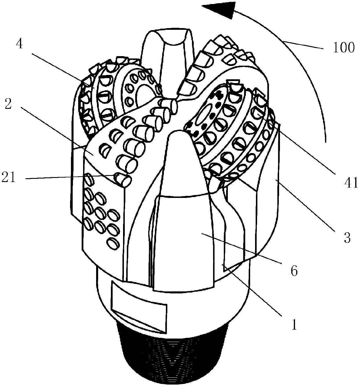
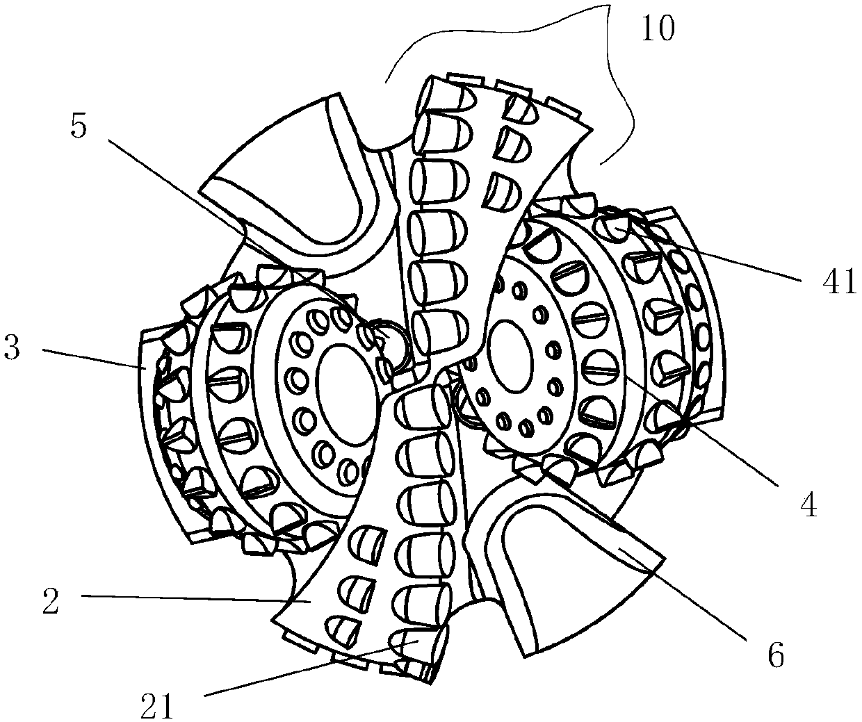
[0082] An embodiment of the present invention provides a composite diamond drill bit with a fixed buffer structure. see figure 1 and figure 2 , The drill bit includes a drill bit body 1, a blade 2, a cone consisting of two cone bodies 4 and teeth 41, a tooth palm 3, a water eye or a nozzle 5, and a buffer seat 6. The blade 2 extends from the drill body 1 or is fixed on the drill body 1 , and scraping teeth 21 are arranged on the blade 2 . A blade 2 is arranged between the front gear and the rear gear, and the buffer seat 6 is independently arranged between the front gear and the blade 2 following rotation.

[0083] see figure 1 , there are only two cones on the drill bit in this embodiment, and each cone can be either a front cone or a rear cone. When one cone is a front cone, the other cone is a rear cone. vice versa. More specifically, if in the drilling direction (item number 100), designate the cone on the palm marked 3 as the front cone, and the other cone following...

Embodiment 2

[0094] The embodiment of the present invention provides a composite drill bit suitable for directional drilling in hard formations. see Figure 14~17 , the drill bit includes a drill bit body 1, a blade 2, a cone consisting of two cone bodies 4 and teeth 41, a tooth palm 3, a water eye or a nozzle 5, and a buffer seat 6. The blade 2 extends from the drill body 1 or is fixed on the drill body 1 , and scraping teeth 21 are arranged on the blade 2 . A blade 2 is arranged between the front gear and the rear gear. The buffer seat 6 is independently arranged between the front toothed wheel and the first blade following its rotation. The working surface of the buffer seat 6 is provided with an accommodating groove 61 and a buffer element 7 , and the buffer element 7 is fixedly connected with the buffer seat 6 through the accommodating groove 61 . in, Figure 17 In the scheme, two blades are arranged between the front gear and the rear gear.

[0095] The cross-sectional shape of ...


PUM


Abstract

The invention discloses a composite diamond drill bit with a fixed buffer structure, and belongs to the field of drilling. The drill bit mainly comprises a drill bit body, multiple cutter wings and atleast two tooth palms extending from the drill bit body or fixed on the drill bit body, and at least two tooth wheels consisting of tooth wheel bodies and teeth, water holes or nozzles; the tooth wheels are rotationally connected with the tooth palms; and scraping teeth are arranged on the cutter wings. For any two adjacent tooth wheels, in the rotating direction of the drill bit, front tooth wheels are on the front side, and back tooth wheels are on the back side; at least one cutter wing is arranged in areas before the back tooth wheels and behind the front tooth wheels; a buffer base extending from the drill bit body or fixed on the drill bit body is arranged between the at last one cutter wing and the front tooth wheels; and a fixed buffer element is arranged on the buffer base. The drill bit can obviously reduce the impact vibration in the guide drilling process, reduces the impact failure of the scraping teeth, and improves the continuous drilling capacity.

Description

technical field [0001] The invention belongs to the field of technical equipment such as oil and gas drilling engineering, mining engineering, building foundation engineering drilling construction, geological drilling, geothermal drilling, hydrological drilling, tunnel engineering, shield tunneling and non-excavation, and in particular relates to a drilling bit. Background technique [0002] Drill bits are rock-breaking tools used to break rocks and form wellbores in drilling engineering. Polycrystalline diamond compact drill bits (PDC bits), roller cone bits and impregnated diamond bits are commonly used. The PDC bit relies on the polycrystalline diamond composite sheet with high hardness, high wear resistance and self-sharpening ability to shear the rock. The PDC bit has the advantages of high penetration rate, long life and low drilling cost in soft to medium hard formations. , It has been widely used in oil and gas exploration, geothermal drilling operations and other pr...

Claims


Application Information

Patent Timeline
IPC IPC(8): E21B10/43E21B10/54E21B12/00
CPCE21B10/43E21B10/54E21B12/00
Inventor 杨迎新张春亮牛世伟任海涛
Owner SOUTHWEST PETROLEUM UNIV
Learn More