A mechanical lock device for connection and positioning

A mechanical lock and guide positioning technology, which is applied to mechanical equipment, connecting components, etc., can solve the problems of high cost and complex structure, and achieve the effect of large load-to-weight ratio, simple structure, and accurate positioning

Active Publication Date: 2020-12-01
HARBIN INST OF TECH
View PDF5 Cites 0 Cited by
  • Summary
  • Abstract
  • Description
  • Claims
  • Application Information

AI Technical Summary

Problems solved by technology

[0003] In order to solve the problem of complex structure and high cost caused by the need to use multiple actuators and detection elements to realize the connection of two mechanisms or equipment, the present invention provides a mechanical lock device for connection and positioning

Method used


Image

  • A mechanical lock device for connection and positioning
  • A mechanical lock device for connection and positioning
  • A mechanical lock device for connection and positioning

Examples


specific Embodiment approach 1

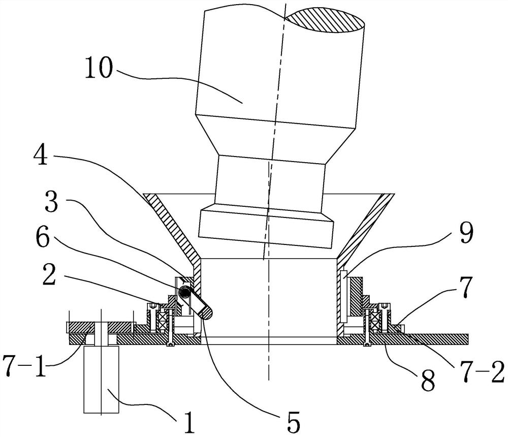
[0020] Specific implementation mode one: combine figure 1 To illustrate this embodiment, this embodiment includes a motor 1, a nut 2, a screw sleeve 3, a guide positioning cylinder 4, a torsion spring 6, a transmission device 7, a base 8 and a plurality of dead bolts 5;

[0021] The motor 1 and the guide and positioning cylinder 4 are respectively fixed on the base 8, the screw sleeve 3 is slidably fitted on the outside of the guide and positioning cylinder 4, the nut 2 is rotated on the base 8 through the transmission device 7 and is threaded with the screw sleeve 3 Cooperate, the motor 1 drives the nut 2 to rotate through the transmission device 7, and each dead bolt 5 is hinged on the screw sleeve 3 by a torsion spring 6, and a plurality of dead bolts 5 are equally distributed on the circumference of the screw sleeve 3, and a plurality of dead bolts 5 Can stretch into the inside of guide positioning cylinder 4.

specific Embodiment approach 2

[0022] Specific implementation mode two: combination figure 1 To illustrate this embodiment, the transmission device 7 in this embodiment includes a driving gear 7-1 and a driven gear 7-2;

[0023] The driving gear 7-1 is connected with the shaft of the motor 1, the driven gear 7-2 is rotated and arranged on the base 8, the driving gear 7-1 and the driven gear 7-2 mesh with each other, and the nut 2 is fixed Connected to the driven gear 7-2, and the nut 2 is arranged concentrically with the driven gear 7-2.

[0024] The present invention adopts gear transmission to ensure the transmission ratio. The position of the screw sleeve 3 is measured by a position sensor such as a potentiometer and transmitted to the input terminal of the PLC. The output terminal of the PLC controls the start and stop of the motor 1 to realize the locking and release of the workpiece 10. The present invention can realize the locking and releasing of the workpiece 10 without particularly high precision...

specific Embodiment approach 3

[0026] Specific implementation mode three: combination figure 1 To illustrate this embodiment, the circumference of the screw sleeve 3 in this embodiment is processed with a plurality of notches, and a lock tongue 5 is arranged in each notch. When the workpiece is in an unlocked state, each groove on the screw sleeve 3 Dead bolt 5 in the mouth is all pressed by torsion spring 6 and is in open state.

[0027] Such arrangement makes it possible for the plurality of lock tongues 5 to change the swinging angle when the screw sleeve 3 passes through the workpiece 10 or the guide positioning cylinder 4, so that the workpiece 10 is in a locked or released state.

[0028] Other compositions and connections are the same as in the first embodiment.


PUM


Abstract

The invention discloses a mechanical locking device for connecting and positioning, and belongs to a locking and positioning device. The mechanical locking device aims to solve the problem that when two mechanisms or equipment are connected, the structure is complex due to the fact that a plurality of execution mechanisms and detection elements need to be adopted. The mechanical locking device comprises a motor, nuts, a screw sleeve, a guide positioning cylinder, torsion springs, a transmission device, a base and a plurality of spring bolts; and the motor and the guide positioning cylinder arecorrespondingly fixed to the base, the screw sleeve is arranged on the outer side of the guide positioning cylinder in a sliding and sleeving mode, the nuts are rotationally arranged on the base through the transmission device and are in threaded fit with the screw sleeve, the motor drives the nuts to rotate through the transmission device, each spring bolt is hinged to the screw sleeve through the corresponding torsion spring, the plurality of spring bolts are uniformly distributed on the circumference of the screw sleeve, and the plurality of spring bolts can extend into the interior of theguide positioning cylinder. The mechanical locking device is suitable for positioning and transferring of trays and the like of the automatic production line.

Description

technical field [0001] The invention relates to a mechanical lock device, in particular to a mechanical lock device for connection and positioning. Background technique [0002] In the industrial field, especially in automation equipment, it is often necessary to have two mechanisms or equipment for docking and pressing applications, which not only need to achieve docking, but also need to meet a certain docking accuracy. The general method is to use more feedback elements to detect the docking and pressing conditions, and drive multiple actuators to complete the docking and pressing actions according to the feedback information, which often results in more complex structures and higher costs. Contents of the invention [0003] The present invention provides a mechanical lock device for connection and positioning in order to solve the problem of complex structure and high cost caused by the need to use multiple actuators and detection elements to realize the connection of ...

Claims


Application Information

Patent Timeline
Patent Type & Authority Patents(China)
IPC IPC(8): F16B21/20
CPCF16B21/20
Inventor 朱映远刘鸿全裴崇鸿刘宏
Owner HARBIN INST OF TECH
Why Eureka
Try Eureka