
Sealed hydraulic tensioner

A technology for sealing hydraulic pressure and tensioners, which is applied in the sealing of engines, machines/engines, transmissions, etc.

Pending Publication Date: 2019-10-22
BORGWARNER INC
View PDF0 Cites 0 Cited by
  • Summary
  • Abstract
  • Description
  • Claims
  • Application Information

AI Technical Summary

Problems solved by technology

However, positioning the chain tensioner relative to the fluid supply provided by the internal combustion engine can limit where on the internal combustion engine the chain tensioner can be positioned

Method used


Image

  • Sealed hydraulic tensioner
  • Sealed hydraulic tensioner

Examples


Embodiment Construction

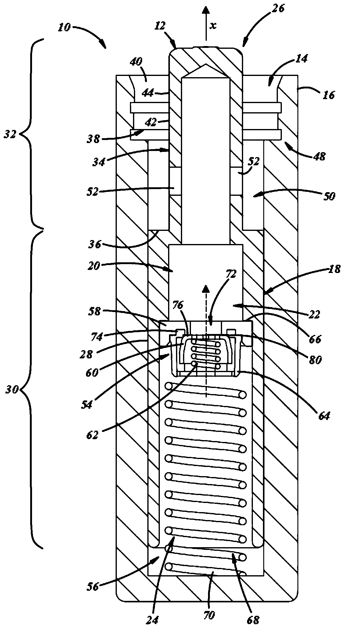
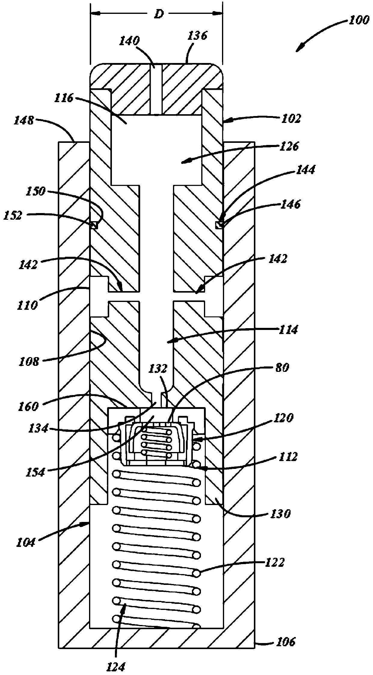
[0009] A sealed hydraulic tensioner includes a cylinder housing a piston that slides relative to the cylinder. The piston may include an inner surface defining a piston cavity. The cylinder and piston combination define an enclosed or sealed space that prevents fluid from escaping from the hydraulic tensioner. A hydraulic tensioner can be divided into a low pressure chamber and a high pressure chamber by means of a check valve and by means of the space between the closely fitting outer surfaces of the cylinder and piston. Fluid can flow between the low and high pressure chambers within the hydraulic tensioner without adding or removing fluid. The piston slides relative to the cylinder to engage the chain and increase the chain's tension around the crankshaft and camshaft sprockets. As the piston slides relative to the cylinder and extends toward the chain, fluid can flow from the low pressure chamber to the high pressure chamber. Fluid can flow from the high-pressure chambe...


PUM


Abstract

A sealed hydraulic tensioner includes a cylinder having a cylinder surface formed in a housing; a piston, received by the cylinder, having an inner surface forming a piston cavity and an outer surfacethat closely conforms in shape to the cylinder inhibiting the flow of fluid between the outer surface of the piston and the cylinder surface; a tensioner biasing member engaging the piston and the cylinder forcing the piston in an axial direction; a check valve regulating fluid flow between a high-pressure chamber and a low-pressure chamber; one or more apertures formed in the piston extending between the inner surface and the outer surface of the piston that communicate fluid between the piston cavity and the cylinder, wherein a substantially fixed quantity of fluid is encapsulated within the piston cavity and the cylinder.

Description

technical field [0001] This application relates to internal combustion engines (ICE), and in particular to hydraulic tensioners for use with internal combustion engines. Background technique [0002] An internal combustion engine has a valve train including a crankshaft and one or more camshafts that receive rotational force of the crankshaft and drive intake / exhaust valves. The rotational output of the crankshaft may be transferred to the camshafts via a chain. The chain may loop around a crankshaft sprocket attached to the crankshaft and one or more camshaft sprockets, each camshaft sprocket attached to one end of the camshaft. The chain linking the crankshaft and camshaft can change length over time, and a chain tensioner can be used to maintain an optimal amount of tension on the chain. [0003] Chain tensioners may be hydraulically driven and rely on the fluid supply provided by the internal combustion engine. For example, engine oil, which is used to lubricate the i...

Claims


Application Information

Patent Timeline
IPC IPC(8): F16H7/08
CPCF16H7/08F16H2007/0812F16H2007/0806F16H2007/0859F02B67/06F16J15/16F16H2007/0893
Inventor K·B·科布M·巴顿陆晓健K·托德D·N·史密斯F·麦格尼R·J·麦尔布希特G·斯旺森G·拜德达丽亚
Owner BORGWARNER INC
Learn More