
Wafer state detection device and method and wafer loading and unloading chamber

A state detection and wafer technology, applied in the direction of transportation and packaging, semiconductor/solid-state device manufacturing, conveyor objects, etc., can solve problems such as occlusion, normal changes, and inability to cause signals, and achieve accurate detection, ease of presence, and area increased effect

Active Publication Date: 2019-10-22
BEIJING NAURA MICROELECTRONICS EQUIP CO LTD
View PDF9 Cites 1 Cited by
  • Summary
  • Abstract
  • Description
  • Claims
  • Application Information

AI Technical Summary

Problems solved by technology

However, in the actual detection process, when the diameter of the laser beam is larger than the thickness of the wafer, the wafer under test cannot block the scanning beam in the effective scanning area and cannot cause signal changes; Under normal circumstances, in the effective scanning area, the wafer under test blocks the scanning beam for a long time, and the normal change of the signal cannot be caused. In these two cases, the distribution state of the wafer cannot be detected correctly.

Method used


Image

  • Wafer state detection device and method and wafer loading and unloading chamber
  • Wafer state detection device and method and wafer loading and unloading chamber

Examples


Embodiment Construction

[0039] In order to enable those skilled in the art to better understand the technical solution of the present invention, the wafer state detection equipment, method and wafer loading and unloading chamber provided by the present invention will be described in detail below with reference to the accompanying drawings.

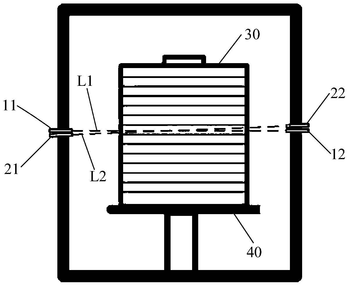
[0040] Such as figure 1As shown, this embodiment provides a wafer state detection device, including a first sensor group, a second sensor group and a control device. Wherein, the first sensor group includes a first emitting sensor 11 and a first receiving sensor 12, the first emitting sensor 11 emits a first light beam L1 to the first receiving sensor 12, and the first light beam L1 is parallel to the plane where the film position of the cassette is located . The second sensor group includes a second emitting sensor 21 and a second receiving sensor 22, the second emitting sensor 21 emits a second light beam L2 to the second receiving sensor 22, and there is a pr...


PUM


Abstract

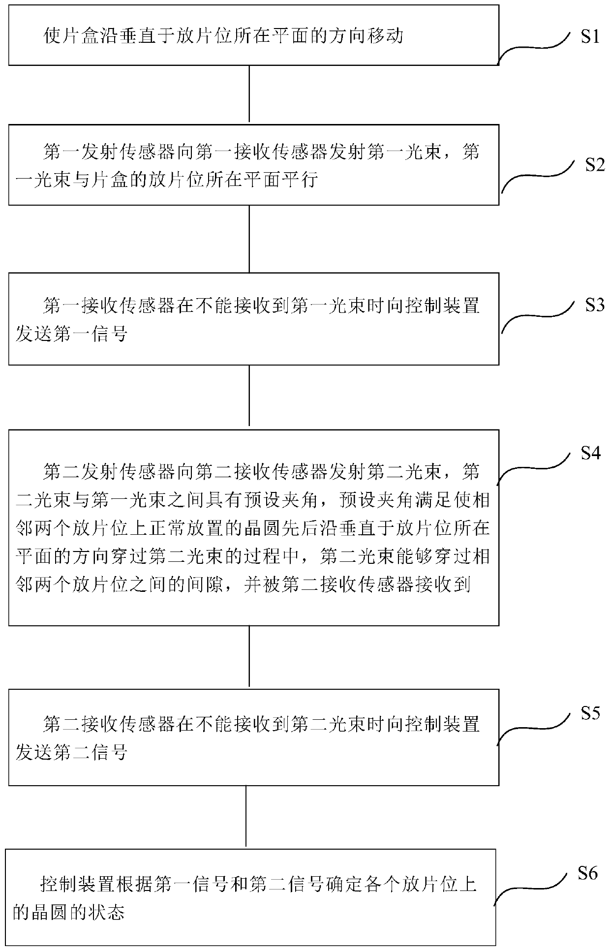
The invention provides a wafer state detection device and method and a wafer loading and unloading chamber. The device comprises a first sensor group, a second sensor group and a control device, wherein the first sensor group includes a first transmitting sensor and a second receiving sensor, the first transmitting sensor transmits a first light beam to the first receiving sensor, and the first light beam is parallel to the plane in which wafer placing positions of a wafer box are located; the second sensor group includes a second transmitting sensor and a second receiving sensor, the second transmitting sensor transmits a second light beam to the second receiving sensor, and a preset included angle is formed between the second light beam and the first light beam; and the control device acquires the state of a wafer at each wafer placing position according to the signal data transmitted by the first receiving sensor and the second receiving sensor. The distribution state of the waferswith different thicknesses can be effectively and accurately detected by adopting the device.

Description

technical field [0001] The invention relates to the field of semiconductor manufacturing, in particular to a wafer state detection device and method, and a wafer loading and unloading chamber. Background technique [0002] At present, in the production process of semiconductor integrated circuits, in order to ensure the efficiency and precision of processing, manipulators are usually used to pick, place and transfer wafers. Specifically, the manipulator control program can formulate the stroke of the manipulator according to the position of the wafer in the wafer cassette (or other container for placing wafers), so as to realize the accurate transfer of the wafer, so the distribution of the wafer in the wafer cassette State data is the key factor to determine whether the manipulator can pick and place wafers accurately. In order to ensure that the manipulator can pick and place wafers normally, the distribution of wafers in the wafer cassette can be detected before the manip...

Claims


Application Information

Patent Timeline
IPC IPC(8): H01L21/67H01L21/677
CPCH01L21/67265H01L21/67778
Inventor 吴启东
Owner BEIJING NAURA MICROELECTRONICS EQUIP CO LTD
Learn More