Winding type asynchronous motor and manufacturing method

An asynchronous motor, winding type technology, applied in the field of motors, can solve problems such as rotation, expansion stress difference, short circuit, etc., to achieve the effect of improving safety performance, reducing expansion stress, and avoiding magnetic short circuit

Inactive Publication Date: 2019-10-22
徐州亚泰电机有限公司
View PDF6 Cites 4 Cited by
  • Summary
  • Abstract
  • Description
  • Claims
  • Application Information

AI Technical Summary

Problems solved by technology

[0010] The invention proposes a winding type asynchronous motor and its manufacturing method, which solves the problems of expansion stress difference between the iron core and the rotating shaft, magnetic short circuit and rotor autorotation after power failure

Method used


Image

  • Winding type asynchronous motor and manufacturing method
  • Winding type asynchronous motor and manufacturing method
  • Winding type asynchronous motor and manufacturing method

Examples


Embodiment 1

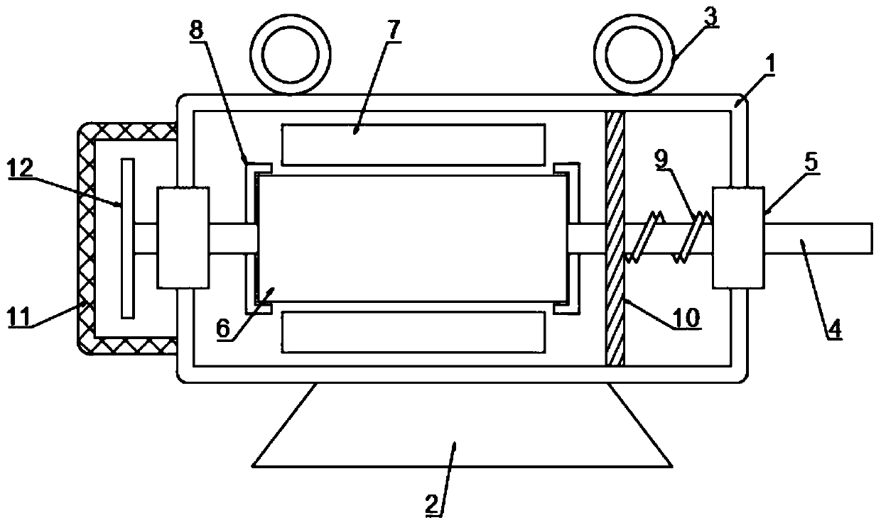
[0039] refer to Figure 1-3 , a wire-wound asynchronous motor, comprising a housing 1, the lower side wall of the housing 1 is integrally formed with a base 2, the upper side wall of the housing 1 is welded with two lifting rings 3, and the inside of the housing 1 is provided with a rotating shaft 4 A rotor 6 is fixed on the outer wall of the rotating shaft 4, and hoops 8 are fixedly sleeved on the outer walls of both ends of the rotor 6. The hoops 8 are mesh structures made of galvanized steel, which can prevent corrosion of steel. rust so as to prolong the service life of the steel, and at the same time have better mechanical performance and enhance the performance of the rotor 6. The inside of the housing 1 is fixed with a stator 7 wound on the outer wall of the rotor 6, and the connection between the housing 1 and the rotating shaft 4 is opened. There is a mounting port, and a bearing 5 is fixed in the mounting port. Both ends of the rotating shaft 4 are inserted through t...

Embodiment 2

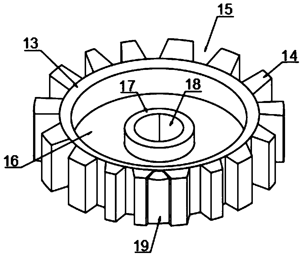
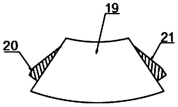
[0048] refer to Figure 2-4 , refer to Figure 1-3 , a wire-wound asynchronous motor, comprising a housing 1, the lower side wall of the housing 1 is integrally formed with a base 2, the upper side wall of the housing 1 is welded with two lifting rings 3, and the inside of the housing 1 is provided with a rotating shaft 4 A rotor 6 is fixed on the outer wall of the rotating shaft 4, and hoops 8 are fixedly sleeved on the outer walls of both ends of the rotor 6. The hoops 8 are mesh structures made of galvanized steel, which can prevent corrosion of steel. rust so as to prolong the service life of the steel, and at the same time have better mechanical performance and enhance the performance of the rotor 6. The inside of the housing 1 is fixed with a stator 7 wound on the outer wall of the rotor 6, and the connection between the housing 1 and the rotating shaft 4 is opened. There is a mounting port, and a bearing 5 is fixed in the mounting port. Both ends of the rotating shaft ...


PUM


Abstract

The invention belongs to the technical field of motors and particularly relates to a winding type asynchronous motor and a manufacturing method. The problems of expansion stress difference between aniron core and a rotating shaft, magnetic short circuit and autorotation of a rotor after a power failure in an existing asynchronous motor are solved. The provided motor comprises a housing; a base isintegrally formed on the lower side wall of the housing; two hanging rings are welded to the upper side wall of the housing; a rotating shaft is arranged in the housing in a penetrating mode; a rotoris fixed to the outer wall of the rotating shaft; a stator arranged on the outer wall of the rotor in a winding mode is fixed in the housing; a mounting opening is formed in the connecting position of the housing and the rotating shaft; and a bearing is fixed in the mounting opening. By arranging the annular iron core, the motor is prevented from contacting the rotating shaft and expansion stressis reduced; by arranging mounting grooves and partition blocks, magnetic contact is avoided, and the electromagnetic performance is guaranteed; and by setting a magnetic plate and a reset spring, therotor is fixed during the power failure, and the safety performance is greatly improved.

Description

technical field [0001] The invention relates to the technical field of motors, in particular to a winding type asynchronous motor and a manufacturing method. Background technique [0002] Wound motors are a type of asynchronous motors. Asynchronous motors are divided into wound type and squirrel cage type according to the rotor winding form. [0003] The working principle of the asynchronous motor is that when the three-phase stator windings (with a phase difference of 120 degrees) of the motor are connected to the three-phase symmetrical alternating current, a rotating magnetic field will be generated, and the rotating magnetic field will cut the rotor winding, thereby generating induction in the rotor winding Current (the rotor winding is a closed path), the current-carrying rotor conductor will generate electromagnetic force under the action of the stator's rotating magnetic field, thereby forming an electromagnetic torque on the motor shaft, driving the motor to rotate,...

Claims


Application Information

Patent Timeline
Patent Type & Authority Applications(China)
IPC IPC(8): H02K1/27H02K1/28H02K9/06H02K7/00H02K15/03H02K15/14
CPCH02K1/274H02K1/28H02K7/003H02K9/06H02K15/03H02K15/14
Inventor 苗培华
Owner 徐州亚泰电机有限公司
Why Eureka
Try Eureka