Method and device for conversion of renewable energy sources

A technology of renewable energy and conversion methods, applied in the direction of electrical components, generators/motors, etc.

Inactive Publication Date: 2019-10-22
刘增民 +2
View PDF0 Cites 0 Cited by
  • Summary
  • Abstract
  • Description
  • Claims
  • Application Information

AI Technical Summary

Problems solved by technology

So far, there is no precedent for using the gravitational interaction of permanent magnets as a renewable energy source

Method used


Image

  • Method and device for conversion of renewable energy sources
  • Method and device for conversion of renewable energy sources
  • Method and device for conversion of renewable energy sources

Examples


Embodiment Construction

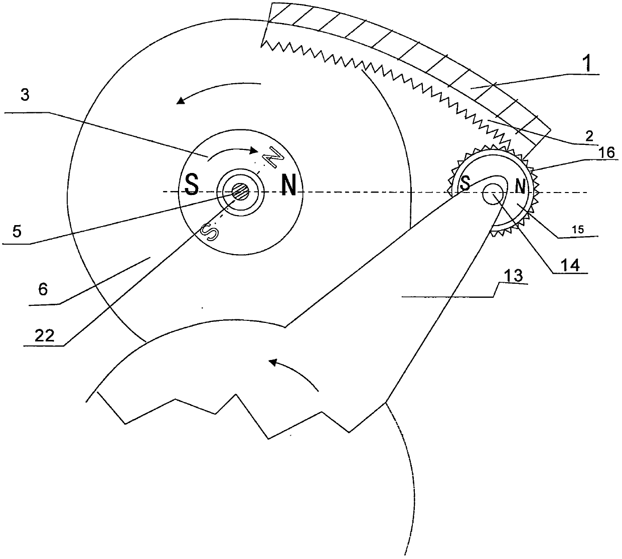
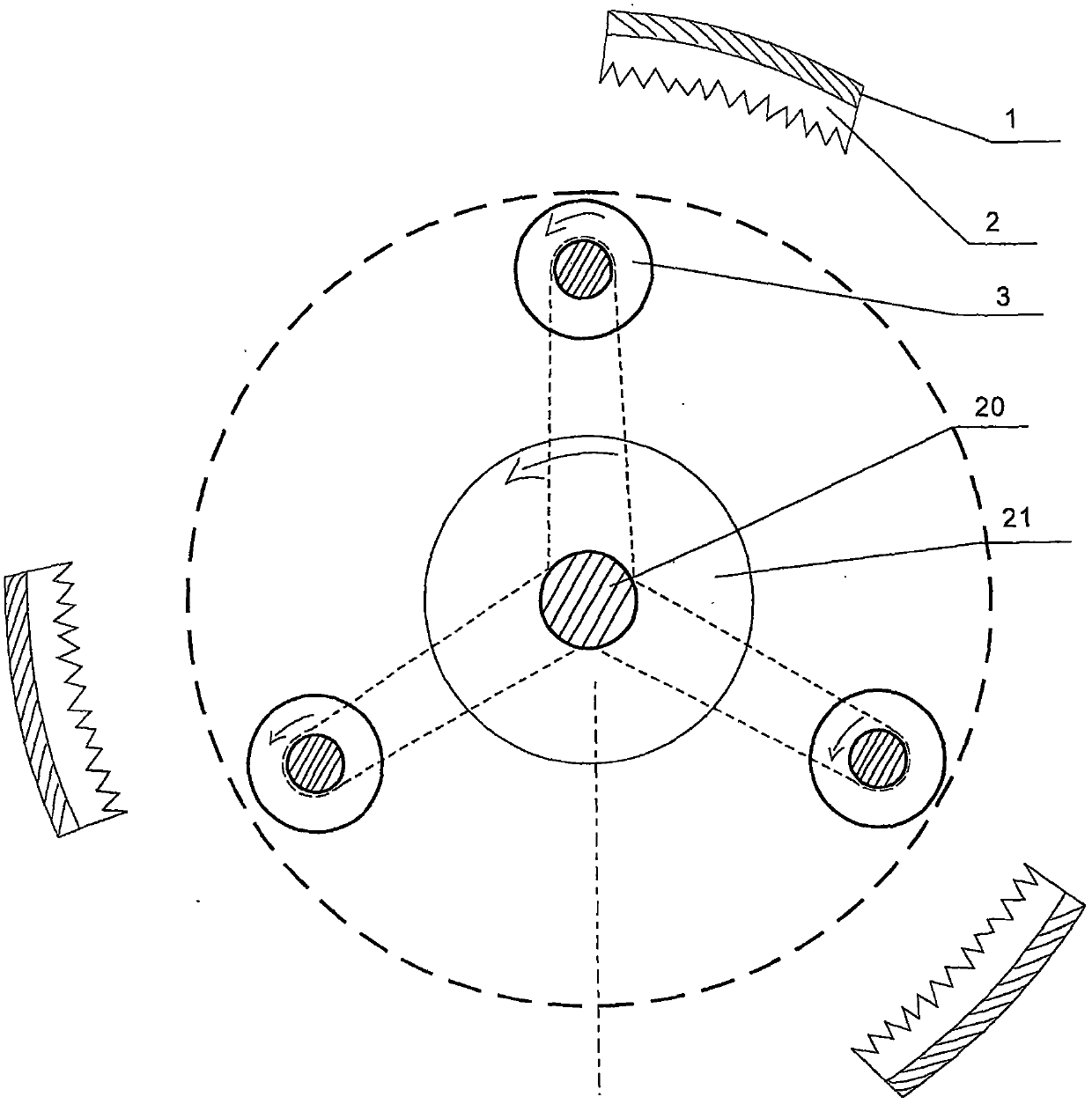
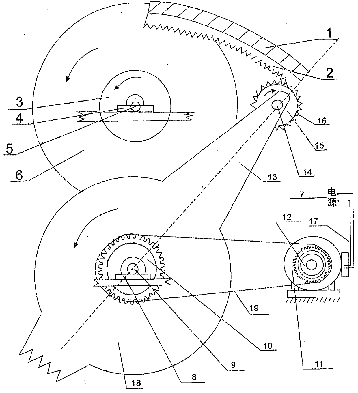
[0020] A method and device for converting renewable energy, such as figure 1 As shown, wherein the inertia wheel 6 is fixedly connected with the wheel shaft 5, the rotation permanent magnet 3 is fixedly connected with the wheel shaft 5, and the two ends of the wheel shaft 5 are fixedly connected with the frame 1 through the bearing tile frame 4 to form a self-rotating rotor mechanism; the revolving wheel 18 It is fixedly connected with the revolving wheel shaft 9, and the two revolving wheel shafts 9 are fixedly connected with the frame 1 through the bearing pad frame 8, and the revolving permanent magnet shaft 14 or the revolving permanent magnet bracket are arranged on the revolving wheel arm 13, and the revolving permanent magnet shaft 14 is fixedly connected with the revolving wheel arm 13, and the revolving permanent magnet 15 is movably installed on the revolving permanent magnet shaft 14, and the revolving permanent magnet 15 is fixedly connected with the revolving gear ...


PUM


Abstract

The invention utilizes the attraction interaction between a rotation permanent magnet and a revolution permanent magnet and converts a distance potential energy between the two permanent magnets intokinetic energy by destroying the symmetry during the mutual attraction. The device comprises a rack, a rotation permanent magnet mechanism, an inertia wheel, a revolution permanent magnet mechanism and a control mechanism.

Description

technical field [0001] The invention relates to a method and device for converting renewable energy, belonging to the field of new energy. Background technique [0002] Although the demand for energy is increasing with the development of industry, the stocks of coal, oil and natural gas on the earth are limited, and they seriously pollute the environment. Human beings urgently need new ideas, new technologies, and find more renewable energy. Energy, solar energy, wind energy, and tidal energy are all renewable energy sources, and have relative infinity. [0003] Tides are caused by the gravitational pull of the earth interacting with the gravitational pull of the moon. We know from textbooks that universal gravitation is a law of nature. The moon revolves around the earth once a month, and a tidal phenomenon is generated so that the seawater flows from the bottom to the high place. People use the method of building a reservoir to store the seawater, and then let the seawat...

Claims


Application Information

Patent Timeline
IPC IPC(8): H02N11/00
CPCH02N11/006
Inventor 不公告发明人
Owner 刘增民
Why Eureka
Try Eureka