Lawn trimming device for landscaping

A lawn mowing and landscaping technology, applied in the field of lawn mowing devices for landscaping, can solve the problems of difficult lawn mowing height adjustment, high usage limitations, increased workload, etc., so as to reduce the residual amount of grass and improve the reliability of use. Sex, the effect of reducing workload

Active Publication Date: 2020-11-06
NANTONG WEIXING TEXTILE TECH CO LTD
View PDF3 Cites 0 Cited by
  • Summary
  • Abstract
  • Description
  • Claims
  • Application Information

AI Technical Summary

Problems solved by technology

[0002] As we all know, the lawn trimming device for landscaping is a device used for trimming the lawn during the maintenance of the garden grass. It can improve the orderliness and aesthetics of the lawn, and it is widely used in the field of lawn trimming devices ; The existing lawn trimming device for landscaping includes a support plate, the left front side, the left rear side, the right front side and the right rear side of the bottom end of the support plate are fixedly equipped with moving wheels, the upper side of the support plate is provided with a first motor, and the support plate A first connection hole is provided on the left side, a first rotating shaft is provided at the output end of the first motor, the bottom end of the first rotating shaft passes through the first connecting hole, and blades are fixedly arranged on the lower side of the left end and the lower side of the right end of the first rotating shaft; When the lawn trimming device for landscaping is in use, the operator pushes the support plate. During the movement of the support plate, the first motor drives the first rotating shaft to rotate. During the rotation of the first rotating shaft, it drives the blade to rotate, and the blade rotates at the same time. Pruning; found in the use of this lawn pruning device for landscaping, it is difficult to adjust the pruning height of the lawn during the pruning process, and the use of the equipment is relatively limited; at the same time, there are more grass leaves remaining on the lawn after pruning, which is for the follow-up handle increased workload

Method used


Image

  • Lawn trimming device for landscaping
  • Lawn trimming device for landscaping
  • Lawn trimming device for landscaping

Examples


Embodiment Construction

[0019] The specific implementation manners of the present invention will be further described in detail below in conjunction with the accompanying drawings and embodiments. The following examples are used to illustrate the present invention, but are not intended to limit the scope of the present invention.

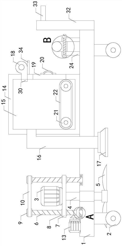
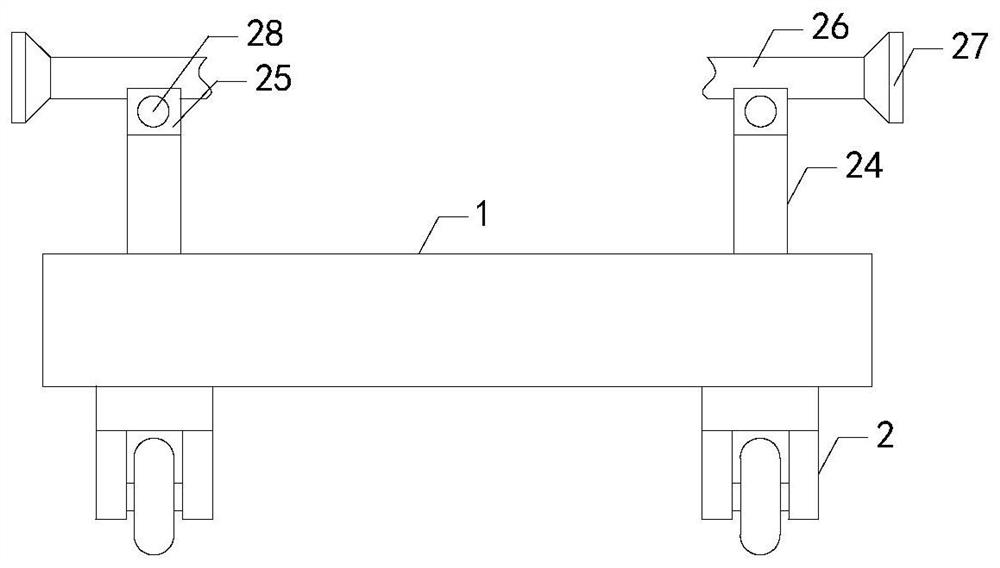
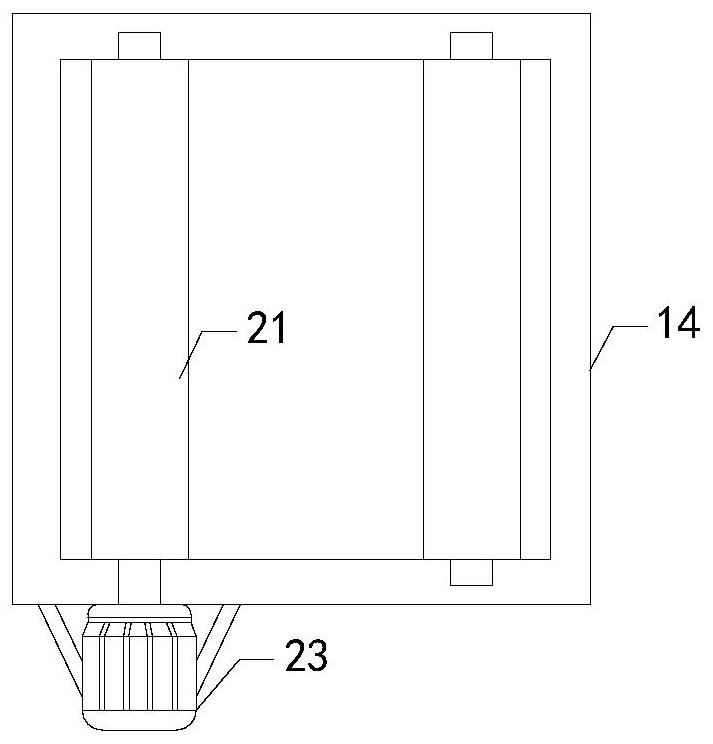
[0020] Such as Figure 1 to Figure 5 As shown, a lawn trimming device for landscaping of the present invention includes a support plate 1, and the left front side, the left rear side, the right front side and the right rear side of the bottom end of the support plate 1 are fixedly equipped with moving wheels 2, and the support plate 1 The first motor 3 is provided on the side, the left side of the support plate 1 is provided with a first connecting hole, the output end of the first motor 3 is provided with a rotating shaft 4, the bottom end of the rotating shaft 4 passes through the first connecting hole, the lower side of the left end of the rotating shaft 4 and the lower...


PUM


Abstract

The invention relates to the technical field of lawn mowing devices, in particular to a lawn mowing device for greening of gardens, which is characterized in that its limit in application can be reduced by adding a height adjusting mechanism, follow-up workload can be reduced by reducing grass blade residues, and its reliability in use can be improved. The lawn mowing device comprises a support plate and further comprises two threaded rods and a collecting box; wheels for moving are fixedly arranged at the left front side, left back side, right front side and right back side of the bottom endof the support plate; a first motor is arranged on the support plate; blades are fixedly arranged at the lower side of the left end and the lower side of the right end of a rotating shaft respectively; top ends of the two threaded rods respectively penetrate the two threaded pipes threadingly; transmission wheels are fixedly arranged at top ends of the two threaded rods and are in transmission connection through a first transmission belt; the lower side of the thread rod at the left is sleeved with a first gear fixedly; the connecting box is provided with an internal cavity, a suction fan is arranged on the upper side of the right end of the collecting box, a damper is arranged in a feed-through opening, and a first handle is fixedly arranged at the right end of the damper.

Description

technical field [0001] The invention relates to the technical field of lawn trimming devices, in particular to a lawn trimming device for landscaping. Background technique [0002] As we all know, the lawn trimming device for landscaping is a device used for trimming the lawn during the maintenance of the garden grass. It can improve the orderliness and aesthetics of the lawn, and it is widely used in the field of lawn trimming devices ; The existing lawn trimming device for landscaping includes a support plate, the left front side, the left rear side, the right front side and the right rear side of the bottom end of the support plate are fixedly equipped with moving wheels, the upper side of the support plate is provided with a first motor, and the support plate A first connection hole is provided on the left side, a first rotating shaft is provided at the output end of the first motor, the bottom end of the first rotating shaft passes through the first connecting hole, and...

Claims


Application Information

Patent Timeline
Patent Type & Authority Patents(China)
IPC IPC(8): A01D43/077A01D69/02A01D69/06
CPCA01D43/077A01D69/02A01D69/06
Inventor 陈迪孙海黄慧
Owner NANTONG WEIXING TEXTILE TECH CO LTD
Why Eureka
Try Eureka