
Automatic hot stamping machine and hot stamping method thereof

A hot stamping machine, automatic technology, applied in the direction of printing machine, transfer printing, rotary printing machine, etc., can solve the problems of lower working efficiency, slow heating and cooling speed of hot stamping roller, uneven heating of film, etc., and achieve improvement Improve work efficiency, reduce operation difficulty, and improve hot stamping effect

Inactive Publication Date: 2019-10-25
浙江智博交通科技有限公司
View PDF0 Cites 1 Cited by
  • Summary
  • Abstract
  • Description
  • Claims
  • Application Information

AI Technical Summary

Problems solved by technology

[0003] 1. The transmission mechanism of the hot stamping roller of the traditional hot stamping machine is relatively complicated. When the hot stamping roller is working, it needs a lot of kinetic energy to drive, and the hot stamping effect is not good. At the same time, it is not easy to control and reduces the work efficiency.
[0004] 2. Traditional hot stamping machines generally heat the film by heating the hot stamping roller, and use the hot stamping roller to heat the film. Since the heating and cooling speed of the hot stamping roller is slow, this method is not only inefficient, but also It is prone to uneven heating of the film, resulting in poor hot stamping effect
[0005] 3. The feeding and discharging of traditional hot stamping machines are generally completed on the same conveyor belt, and the direction of feeding and discharging is consistent. It requires the cooperation of multiple people to complete the hot stamping, and the material needs to be manually taken out from the bottom of the hot stamping roller when discharging. more dangerous

Method used


Image

  • Automatic hot stamping machine and hot stamping method thereof
  • Automatic hot stamping machine and hot stamping method thereof
  • Automatic hot stamping machine and hot stamping method thereof

Examples


Embodiment

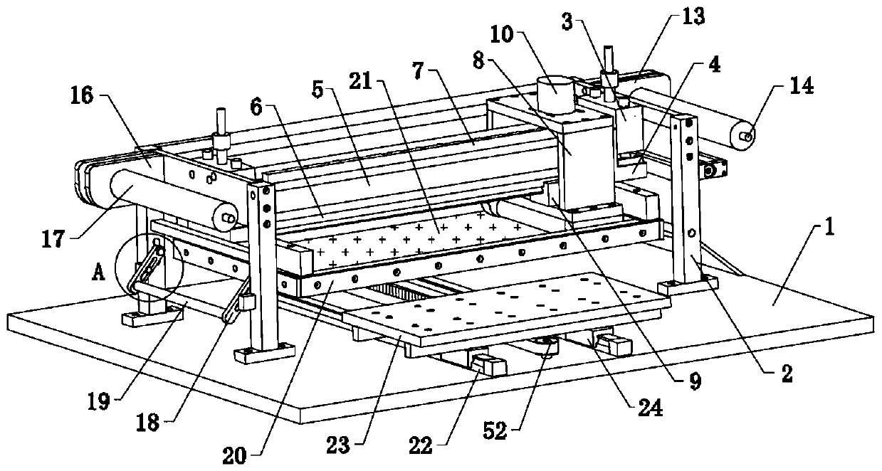
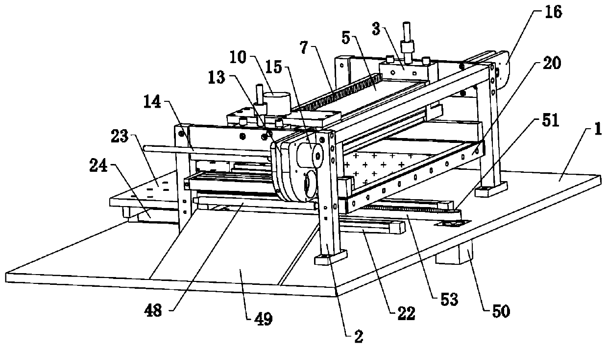
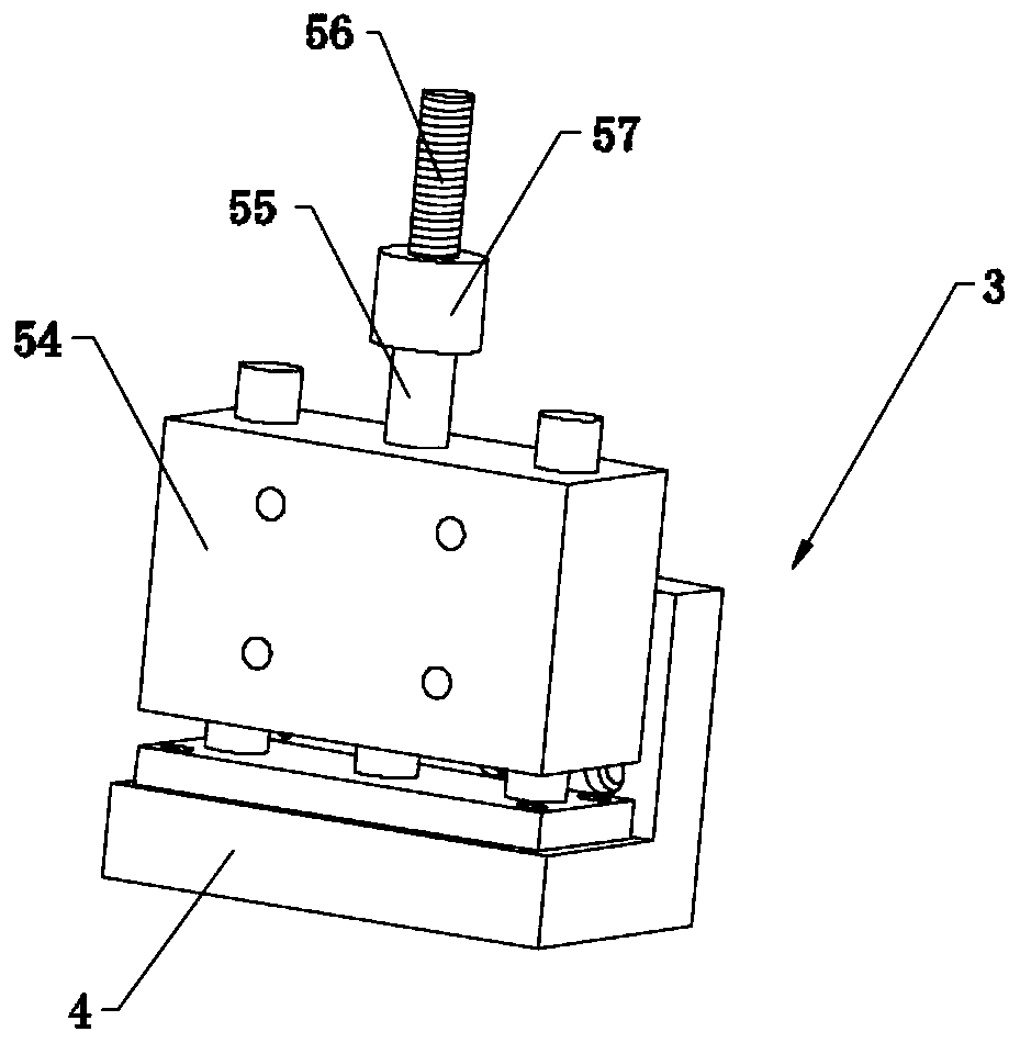
[0041] Embodiment: a kind of automatic hot stamping machine, constitutes as Figure 1-2 As shown, including workbench 1, the top of workbench 1 is provided with frame 2, and the inner side of two ends of frame 2 is symmetrically provided with telescopic driver 3, and the end of each telescopic driver 3 is provided with lifting plate 4, two A crossbeam 5 is provided between the lifting plates 4, and a transmission roller mechanism is arranged on the crossbeam 5; a heating sheet holder 20 is provided at the bottom of the two lifting plates 4, and a heating sheet holder 20 is provided at the middle of the heating sheet holder 20 and is located below the transmission roller mechanism. Silicone heating plate 21; a film transmission mechanism fixed on the frame 2 is provided under the beam 5; a feeding mechanism vertically arranged to the film transmission mechanism is also provided on the workbench 1.

[0042] like image 3 As shown, the telescopic driver 3 includes a cylinder 54 ...


PUM


Abstract

The invention discloses an automatic hot stamping machine and a hot stamping method thereof. The automatic hot stamping machine comprises a workbench, wherein the top of the workbench is provided witha rack; the inner sides of two ends of the rack are symmetrically provided with telescopic driving parts; the end part of each telescopic driving part is provided with a lifting plate; a cross beam is arranged between the two lifting plates, and the cross beam is provided with a transmission press roller mechanism; the bottoms of the two lifting plates are provided with heating sheet frames, andthe middle parts of the heating sheet frames are provided with silica gel heating sheets which are positioned at the lower parts of the transmission compression roller mechanisms; a film transmissionmechanism fixed on the rack is arranged at the lower part of the cross beam; and the workbench is also provided with a feeding mechanism which is vertical to the film transmission mechanism. Accordingto the machine, the abovementioned whole structure is adopted, so that the feeding process is simple, and the convenience of control is ensured; a film can be uniformly heated, thus the hot stampingeffect is improved, and meanwhile, the operation steps are simplified, and the operation difficulty is reduced.

Description

technical field [0001] The invention belongs to the technical field of hot stamping of license plates, and in particular relates to an automatic hot stamping machine and a hot stamping method thereof. Background technique [0002] The production process of the license plate is to press the license plate, that is, to press the number or letter of the license plate number, so that the number or letter protrudes from the surface of the license plate, and then use the hot stamping machine to cover the film with ink on the license plate for hot stamping. Hot stamp ink on the surface of numbers or letters. Traditional hot stamping machines have the following problems: [0003] 1. The transmission mechanism of the hot stamping roller of the traditional hot stamping machine is relatively complicated. When the hot stamping roller is working, it needs a lot of kinetic energy to drive, and the hot stamping effect is not good. At the same time, it is not easy to control and reduces the...

Claims


Application Information

Patent Timeline
Patent Type & Authority Applications(China)
IPC IPC(8): B41F16/00
CPCB41F16/0026B41F16/006B41F16/0073B41F16/0093B41P2217/10B41P2217/50
Inventor 黄小良何振华
Owner 浙江智博交通科技有限公司
Learn More