
Fast joint for high pressure variable frequency water pump in mine environment

A frequency conversion water pump, medium and high pressure technology, applied in the direction of mechanical equipment, couplings, etc., can solve the problems of poor sealing, difficult to achieve fast alignment connection, not smooth and convenient connection, etc., to achieve the effect of reducing resistance

Active Publication Date: 2019-10-25
台州市千喜泵业有限公司
View PDF6 Cites 0 Cited by
  • Summary
  • Abstract
  • Description
  • Claims
  • Application Information

AI Technical Summary

Problems solved by technology

[0006] In order to solve the above-mentioned technical problems, the present invention provides a quick connector for a high-voltage variable-frequency water pump in a mine environment, to solve the existing problem that the connection is not smooth enough and convenient, and the end faces of the existing quick structure are all planar structures, especially in mines, etc. In an environment with limited lighting conditions, it is difficult to achieve fast alignment connection; moreover, the structure is not reasonable enough, and the existing quick connectors, such as snap-on connectors through snap beads, have not been equipped with corresponding protective structures. Inadvertently touching the ferrule during the process to displace the ferrule will easily cause the male and female parts of the joint to separate from each other; finally, the sealing performance is poor. After the existing device is connected, water leakage is prone to occur in the connection gap between the male and female heads question

Method used


Image

  • Fast joint for high pressure variable frequency water pump in mine environment
  • Fast joint for high pressure variable frequency water pump in mine environment
  • Fast joint for high pressure variable frequency water pump in mine environment

Examples


Embodiment

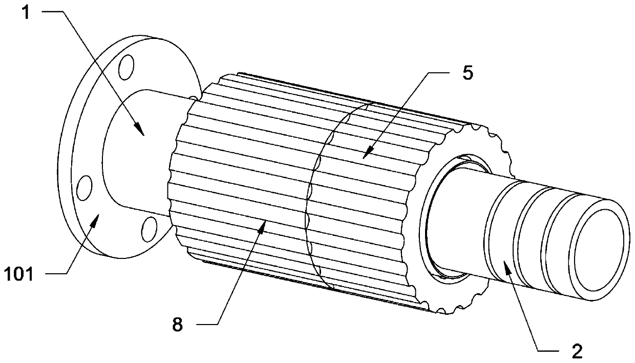
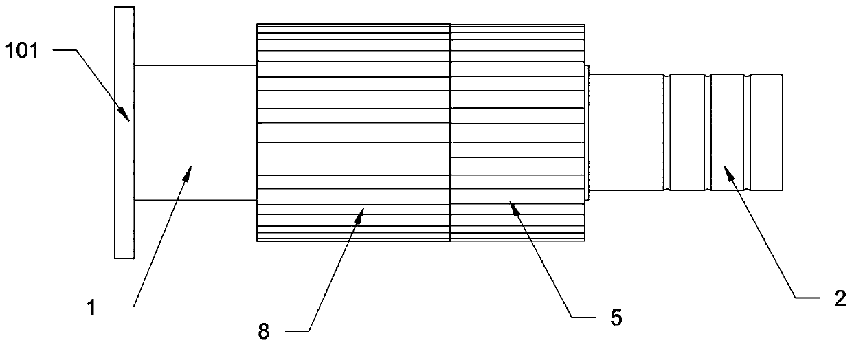
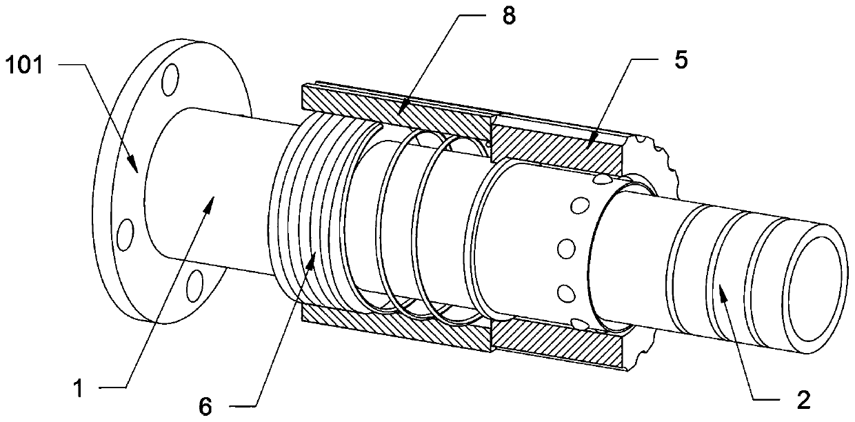
[0035] as attached figure 1 to attach Figure 8 Shown:

[0036] The invention provides a quick joint for a high-voltage frequency conversion water pump in a mine environment, including a joint seat 1, a fixed seat 101, a tapered groove A102, a joint body 2, a card slot A201, a card slot B202, a card bead 3, a retaining ring 4, and a card sleeve 5 , stud 6, spring 7, limit nut 8, annular stopper 9, tapered groove C901 and rubber pad 10; the joint seat 1 is a cylindrical tubular structure, and the rear end surface of the joint seat 1 is welded with an annular The fixed seat 101, and the front side of the outer wall of the joint seat 1 is provided with ten snap beads 3 for matching with the slot A201 in an annular array; the joint main body 2 is a cylindrical tubular structure, and the joint main body 2 There is a card slot A201 matching the card bead 3 at the front side of the outer wall; a stop ring 4 is welded on the outer wall of the joint seat 1, and a ferrule 5 is sleeved...


PUM


Abstract

The invention provides a fast joint for a high pressure variable frequency water pump in a mine environment. A joint base, a conical groove C and a rubber pad are included; the joint base is of a cylindrical pipe-shaped structure; an annular fixed base is welded to the rear end face of the joint base; ten clamping beads used for being matched with a clamping groove A are arranged on the front sideof the outer wall of the joint base in an annular array shape; a stud is welded to the position, located on the rear side of a check ring, of the outer wall of the joint base; and the position, located between the stud and a clamping sleeve, of the outer wall of the joint base is sleeved with a spring. Due to the fact that the front end face of the joint base is provided with a conical groove A,clamping can be reduced during mutual connection of a joint body and the joint base in the using process. Compared with an existing device, during connection of the device, operation is more smooth and convenient; due to the arrangement of the clamping sleeve, the stud and a limiting nut, the limiting nut is screwed so that the clamping sleeve can be limited. Compared with the existing device, after connection of the device, in use, the situation that due to accidental touching, the position of the clamping sleeve is moved, and consequently the joint body and the joint base disengage from eachother can be prevented.

Description

technical field [0001] The invention belongs to the technical field of pipeline connection, and more specifically relates to a quick joint for a high-pressure variable-frequency water pump in a mine environment. Background technique [0002] A quick connector is a connector that can be connected or disconnected without tools. Quick connectors can be divided into: quick connectors for air, quick connectors for oxygen fuel gas, quick connectors for gas and liquid, quick connectors for oil pressure, quick connectors for inert gas, quick connectors for cooling water and oil, and semiconductor quick connectors. [0003] For example, the application number: CN201210428006.X, the invention belongs to the field of pipeline connection, especially a quick connector for gas, liquid and other fluids and valves, including three major parts: a connecting body, a sealing ring, and a multifunctional movable sleeve. The large part structure can be freely assembled, disassembled and replaced...

Claims


Application Information

Patent Timeline
IPC IPC(8): F16L37/084
CPCF16L37/084
Inventor 冯帅
Owner 台州市千喜泵业有限公司
Learn More