
Experimental test device based on true crack state and test method thereof

A technology of experimental testing and real state, which is applied in the direction of measuring devices, optical testing flaws/defects, instruments, etc., can solve the problems of difficult sampling of deep cracks, difficult testing, large testing errors, etc., to facilitate timely processing, increase reliability, The effect of increasing precision

Inactive Publication Date: 2019-10-25
CHINA INST OF WATER RESOURCES & HYDROPOWER RES +1
View PDF7 Cites 8 Cited by
  • Summary
  • Abstract
  • Description
  • Claims
  • Application Information

AI Technical Summary

Problems solved by technology

[0003] At present, the commonly used crack depth detection methods in engineering inspection are destructive method and non-destructive method. The destructive method refers to the intuitive and effective method of drilling and coring. Cracks are often difficult to test due to sampling difficulties
Non-destructive methods include ultrasonic method (including flat measurement method, oblique measurement method and countermeasure method), surface wave method (phase inversion method, propagation time difference method), but due to the influence of crack surface contact, steel bars, moisture and signal attenuation , the wave will pass through in advance, and the propagation time of the test will be shortened, so that the fracture depth obtained by the standard test method is often shallower than the actual value, especially for deep fractures, the test error is greater

Method used


Image

  • Experimental test device based on true crack state and test method thereof
  • Experimental test device based on true crack state and test method thereof
  • Experimental test device based on true crack state and test method thereof

Examples


Embodiment

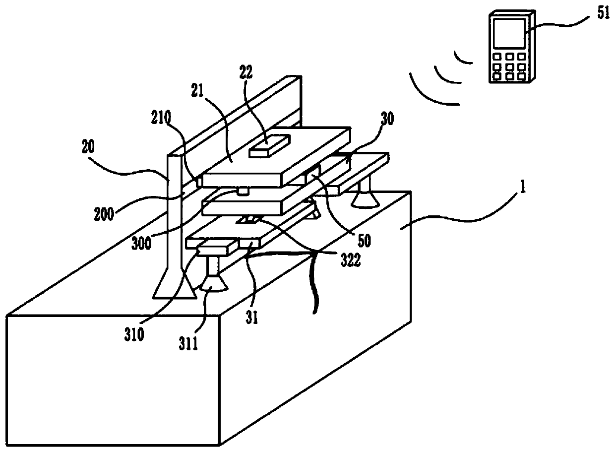
[0033] Example: such as figure 1 As shown, a test device based on the real state of cracks mainly includes a concrete block 1, a position adjustment element 2, a fixed element 3, a crack test element 4, an intelligent control element 5, and a power supply device; crack;

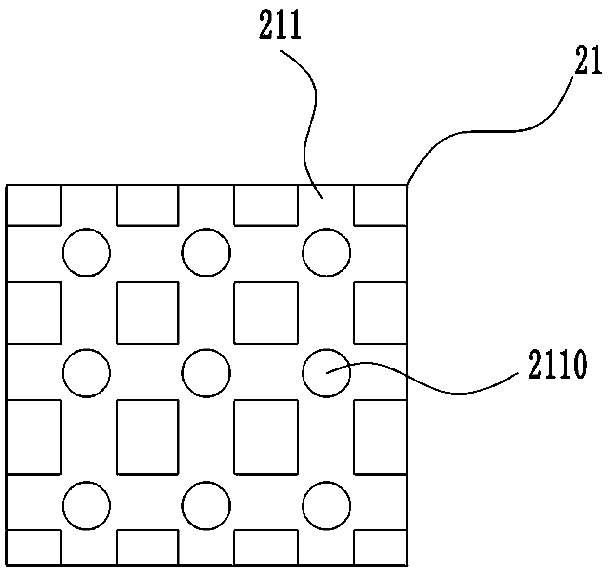
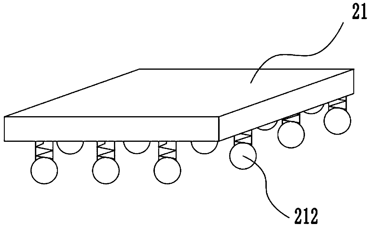
[0034] Such as figure 2 As shown, the position adjustment element 2 includes a mounting vertical plate 20 fixed on the concrete block 1 with a sliding groove 200 on the side along the horizontal direction, a chute moving plate 21 whose side wall is connected to the sliding groove 200 through a sliding block 210, and a driving sliding The drive motor one 22 that block 210 moves in slide groove 200, the bottom side of chute moving plate 21 is provided with the mesh groove 211 that is made of vertical groove and horizontal groove, vertical groove and horizontal groove intersect on mesh groove 211 There is a clamping hole 2110 at the bottom of the sliding column 300, and a sliding ball 301 is provided at the b...


PUM


Abstract

The invention discloses an experimental test device based on a true crack state and a test method thereof and belongs to the concrete non-destructive test and repair reinforcement technology field. The device mainly comprises a concrete block, a position adjustment component, a fixing component, a crack test component, an intelligent control component, and a power supply device. By fixing a component structure, a crack shooting camera can be taken in when the camera is not used so as to avoid a condition that scratches of a lens caused by an external environment can affect a shooting effect. Through the crack test component and the intelligent control component, an energy reduction amplitude of an ultrasonic signal in a crack test process is obtained so as to calculate a crack depth, safety of a tested structure is evaluated according to the crack depth, remedial measures are obtained, and work reliability of a device is improved. The crack test device of the invention can convenientlycarry out remote crack testing through the intelligent control component, and a test data change value is timely transmitted to an external controller so that monitoring personnel can timely grasp arelevant situation of a crack and timely processing becomes convenient.

Description

technical field [0001] The invention belongs to the technical field of non-destructive detection and repairing and strengthening of concrete, and in particular relates to a test device and a test method based on the real state of cracks. Background technique [0002] Concrete structures are the most important civil, hydraulic and architectural structures and play a pivotal role in social infrastructure. However, due to various reasons (such as drying shrinkage, temperature stress, external load, foundation deformation, etc.), concrete produces cracks, and cracks are the most common defect or damage phenomenon in concrete structures. Due to the different causes, states, development and positions in the structure of cracks, the harmfulness to the structure is also very different. Severe cracks may endanger the integrity and stability of the structure, and have a great impact on the safe operation of the structure. On the other hand, there are also some cracks, such as shallo...

Claims


Application Information

Patent Timeline
Patent Type & Authority Applications(China)
IPC IPC(8): G01N21/95G01B17/00
CPCG01B17/00G01N21/95
Inventor 王荣鲁岳跃真秦明豪赵妍孙粤琳张家宏刘致彬徐耀李蓉邱信蛟李秀琳孟丽娟刘敬洋柳振华杨述王禹迪
Owner CHINA INST OF WATER RESOURCES & HYDROPOWER RES
Learn More