
Three level gate monitoring

A grid control and grid technology, applied in program control, computer control, general control system, etc., can solve problems such as component aging, overheating, humidity, dust, mechanical stress, equipment failure, etc.

Active Publication Date: 2019-10-25
INFINEON TECH AG
View PDF25 Cites 0 Cited by
  • Summary
  • Abstract
  • Description
  • Claims
  • Application Information

AI Technical Summary

Problems solved by technology

[0004] Although semiconductor ICs generally have high reliability, due to various reasons (such as component aging, exposure to adverse environments (eg, excessive heat, humidity, dust, mechanical stress), or improper use (eg, overvoltage or undervoltage)) , equipment failures still occur over time

Method used


Image

  • Three level gate monitoring
  • Three level gate monitoring
  • Three level gate monitoring

Examples


example 1

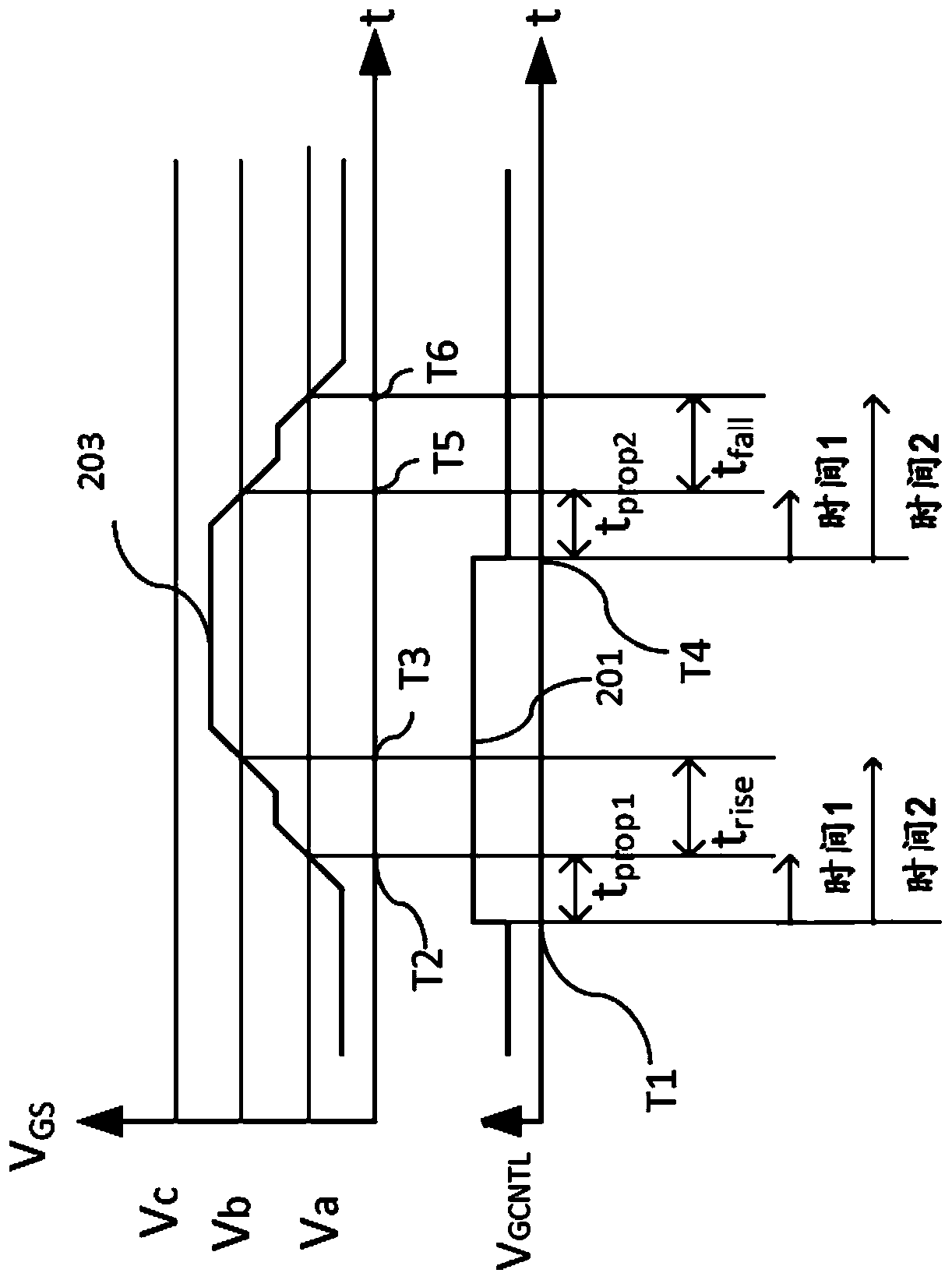
[0073] Example 1. In one embodiment, a method of monitoring the gate of a transistor comprises: monitoring the gate voltage of the transistor; and based on the monitoring, measuring the time at which the gate control signal is asserted and the gate voltage of the transistor versus a first voltage threshold a first time difference between the moments of crossing; based on monitoring, measuring a second time difference between the moment when the gate voltage of the transistor crosses the first voltage threshold and the moment when the gate voltage of the transistor crosses the second voltage threshold; and determining Whether the first time difference falls within the first time window and whether the second time difference falls within the second time window.

example 2

[0074] Example 2. The method of Example 1, further comprising: asserting an error signal when the first time difference falls outside a first time window or when the second time difference falls outside a second time window.

example 3

[0075] Example 3. The method of Example 2, further comprising disabling a driver coupled to the gate of the transistor when the false signal is asserted.


PUM


Abstract

The invention relates to three level gate monitoring. A method of monitoring a gate of a transistor includes monitoring a gate voltage of the transistor; measuring a first time difference between whena gate control signal is asserted and when the gate voltage of the transistor crosses a first voltage threshold based on the monitoring; measuring a second time difference between when the gate voltage of the transistor crosses the first voltage threshold and when the gate voltage of the transistor crosses a second voltage threshold based on the monitoring; and determining whether the first timedifference falls within a first time window, and whether the second time difference falls within a second time window.

Description

technical field [0001] The present disclosure relates generally to electronic circuits and systems, and in particular, to power control circuits and methods of operating the power control circuits. Background technique [0002] Power control circuitry may include power management circuitry, driver circuitry, control logic, diagnostic logic, or other circuitry. Power management circuitry may be used to generate and / or regulate supply voltages. Drive circuits can be used to control devices that generate power, such as switched mode power supplies, and can be used to control devices that consume power, such as electric motors. The motor driver may have a controller that generates pulse width modulated signals that are used to generate drive signals for the driver switches of the different phases of the motor. The pulse width modulated signal may be generated based in part on the component's internal oscillator. [0003] The power control circuit may be implemented as an inte...

Claims


Application Information

Patent Timeline
IPC IPC(8): G05B19/048H03K17/687
CPCG05B19/048H03K17/687H03K17/18H02M1/32G01R19/16538G01R19/1659G01R31/2621H03K2017/0806H03K17/08122H02M1/08G01R19/16519
Inventor M·扎诺斯J·梅杰里
Owner INFINEON TECH AG
Features
  • Generate Ideas
  • Intellectual Property
  • Life Sciences
  • Materials
  • Tech Scout
  • Unparalleled Data Quality
  • Higher Quality Content
  • 60% Fewer Hallucinations
Learn More