Retention time violation repair method, device and equipment

A hold time and violation technology, applied in the field of hold time violation repair, can solve the problems of multi-trace resources, occupation, scan chain hold time violation deterioration, etc., to achieve the effect of reducing iteration cycle and design impact

Active Publication Date: 2019-10-25
LOONGSON TECH CORP
View PDF12 Cites 17 Cited by
  • Summary
  • Abstract
  • Description
  • Claims
  • Application Information

AI Technical Summary

Problems solved by technology

[0005] The present invention provides a hold time violation repair method, device and equipment to solve the problem that there is not enough space to insert a buffer in the hold time repair stage, or the newly inserted buffer can only be placed far away from the target area, resulting in scanning The path will occupy more routing resources. On the one hand, the setup time violation of the functional path will be increased. On the other hand, the winding or long trace is more susceptible to coupling noise, which will lead to the deterioration of the scan chain hold time violation.

Method used


Image

  • Retention time violation repair method, device and equipment
  • Retention time violation repair method, device and equipment
  • Retention time violation repair method, device and equipment

Examples


Embodiment 1

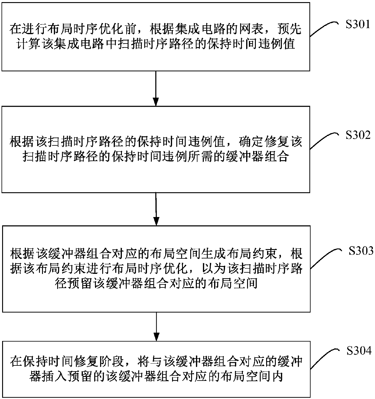
[0057] image 3 It is a flowchart of a method for repairing a hold time violation provided in Embodiment 1 of the present invention. In the embodiment of the present invention, there is not enough space to insert buffers in the hold time repair stage, or the newly inserted buffers can only be placed far away from the target area, resulting in the scan path occupying more routing resources. On the one hand, it increases The setup time of the functional path is violated. On the other hand, winding or long traces are more susceptible to coupling noise, which leads to the deterioration of the hold time violation of the scan chain. A repair method for the hold time violation is provided. Such as image 3 The specific steps of the method are as follows:

[0058] Step S301 , before performing layout timing optimization, precalculate the hold time violation value of the scan timing path in the integrated circuit according to the netlist of the integrated circuit.

[0059] Wherein, ...

Embodiment 2

[0073] Figure 4 It is a flowchart of a method for repairing a hold time violation provided in Embodiment 2 of the present invention. On the basis of the first embodiment above, in this embodiment, according to the netlist of the integrated circuit, calculating the hold time violation value of the scan timing path in the integrated circuit includes: extracting the scan timing path information and the current clock from the netlist Tree topology information; according to the scan timing path information and the topology information of the current clock tree, calculate the clock delay difference between the start timing device and the end timing device of the scan timing path; according to the start timing device information and the end timing device Information to determine the data delay of the start sequential device and the hold time of the end sequential device; according to the clock delay difference between the start sequential device and the end sequential device of the ...

Embodiment 3

[0134] Figure 5 A schematic structural diagram of a device for repairing hold time violations provided by Embodiment 3 of the present invention. The device for repairing a hold time violation provided in the embodiment of the present invention can execute the processing procedure provided in the embodiment of the method for repairing a hold time violation. Such as Figure 5 As shown, the device 50 includes: a calculation module 501 , a determination module 502 , an optimization module 503 and a repair module 504 .

[0135] Specifically, the calculation module 501 is configured to pre-calculate the hold time violation value of the scan timing path in the integrated circuit according to the netlist of the integrated circuit before performing layout timing optimization.

[0136] The determining module 502 is configured to determine a buffer combination required to fix the hold time violation of the scan timing path according to the hold time violation value of the scan timing ...


PUM


Abstract

The invention provides a retention time violation repairing method, device and equipment. The method includes: before layout time sequence optimization, calculating a retention time violation value ofa scanning time sequence path in an integrated circuit in advance according to a netlist of the integrated circuit; determining a buffer combination required for repairing the retention time violation of the scanning time sequence path according to the retention time violation value of the scanning time sequence path; generating a layout constraint according to the layout space corresponding to the buffer combination, and performing layout time sequence optimization according to the layout constraint to reserve the layout space corresponding to the buffer combination for the scanning time sequence path; during a hold time repair phase, inserting the buffer corresponding to the buffer combination into the layout space corresponding to the reserved buffer combination, and the newly insertedbuffer is located in the reserved layout space, so that the placement of the original unit is not influenced, too many wiring resources are not increased, the influence on the design is minimum, andthe iterative period of the design can be remarkably shortened.

Description

technical field [0001] The invention relates to the technical field of integrated circuits, in particular to a method, device and equipment for repairing hold time violations. Background technique [0002] Hold time repair is an important link in integrated circuit design, and this process directly affects the speed, power consumption, and area of ​​the final circuit. The hold time of the scan chain timing path is the main component of the overall circuit hold time violation. Inserting buffers to increase path delay is a common way to fix hold time. [0003] The traditional design process of integrated circuits includes: netlist generation and layout and layout timing optimization, clock tree construction, hold time repair, routing and post-routing timing optimization, layout output and other stages. Among them, the layout phase determines the physical position and orientation of all standard cells and macro cells (Macro), and the layout and layout timing optimization perf...

Claims


Application Information

Patent Timeline
Patent Type & Authority Applications(China)
IPC IPC(8): G06F17/50
CPCG06F30/392
Inventor 肖斌王昊
Owner LOONGSON TECH CORP
Why Eureka
Try Eureka