A combined air cooling device for subway traction converter

A traction converter and air-cooling device technology, applied in the field of rail transit, can solve the problems of rising temperature of power devices, low heat flux density of radiators, and inability of heat exchange devices to effectively dissipate heat.

Active Publication Date: 2021-04-20
XIAN YONGDIAN ELECTRIC
View PDF4 Cites 0 Cited by
  • Summary
  • Abstract
  • Description
  • Claims
  • Application Information

AI Technical Summary

Problems solved by technology

[0004] However, the following problems still exist in the prior art: 1) The heat flux density of the heat sink passively dissipated by the running wind is low, and more heat-generating power devices cannot be arranged on the heat sink substrate of the same area; 2) the finned heat sink with heat pipe The radiator device is bulky, because it needs to use the traveling wind to dissipate heat. In order to ensure the heat dissipation efficiency, the internal radiator needs to design larger fins and heat pipes to increase the contact area with the traveling wind, resulting in a large radiator; 3 ) When the subway vehicle stops running, it will not be able to generate sufficient speed of running wind, and the heat exchange device will not be able to effectively dissipate heat; 4) The heat dissipation efficiency of the existing scheme cannot be adjusted independently: the heat dissipation efficiency of the existing scheme is affected by the speed of the running wind, especially for the subway When the vehicle starts to accelerate, the traction converter generates a lot of heat. When the wind speed is low, the traction converter heat accumulates and the temperature of the power device rises rapidly.

Method used


Image

  • A combined air cooling device for subway traction converter
  • A combined air cooling device for subway traction converter
  • A combined air cooling device for subway traction converter

Examples


Embodiment 1

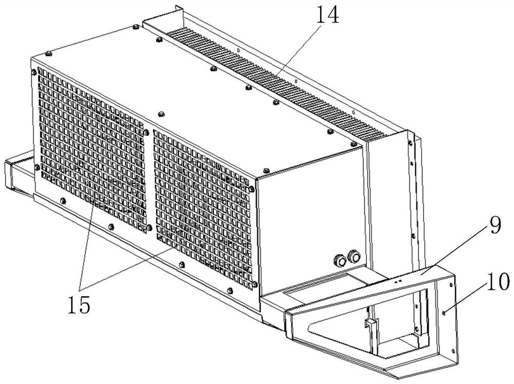
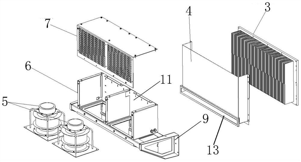
[0029] see Figure 1-3 As shown, the present invention provides a combined air-cooling device for subway traction converters, which includes a detachable air inlet assembly 1 and an air outlet assembly 2, and the air inlet assembly 1 and the air outlet assembly 2 are connected through an air duct connection; The air inlet assembly 1 includes a radiator 3 and an air inlet cover 4, and the radiator 3 and the air inlet cover 4 are detachably connected; the air outlet assembly 2 includes an adjustable-speed cooling fan assembly 5, a fan frame assembly 6, and a fan cover The plate 7 and the adjustable-speed cooling fan assembly 5 are installed in the fan frame assembly 6 , and the fan cover plate 7 is detachably connected with the fan frame assembly 6 .

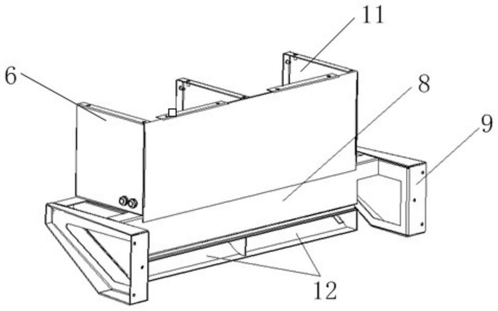
[0030] Further, the fan frame assembly 6 includes a trapezoidal air duct body 8, the two ends of the trapezoidal air duct body 8 are provided with mounting feet 9, the top of the trapezoidal air duct body 8 is provided with a fan ...

Embodiment 2

[0042] On the basis of Embodiment 1, the present invention also provides a practical application schematic diagram of a combined air-cooling device for a subway traction converter, see Figure 5 shown. The combined air-cooling device is used as a whole to dissipate heat from the IGBT power device 17. The adjustable-speed cooling fan assembly 5 is an adjustable-speed centrifugal fan assembly. The fan frame assembly 6 consists of two mounting feet, a trapezoidal air duct body 8 and Two fan assembly installation parts 11 are formed, and the working process of the whole air cooling device is as follows:

[0043] The combined air cooling device is assembled into a whole, and the IGBT power device 17 inside the converter is directly fixed on the radiator substrate 16; the air cooling device is connected to the traction converter through the mounting feet 9 on both sides of the air outlet assembly On the cabinet body of the converter, the heat generated by the IGBT power device 17 i...

Embodiment 3

[0045] On the basis of Embodiment 1, the present invention further provides a practical application schematic diagram of a combined air-cooling device for a subway traction converter after being split into an air inlet assembly and an air outlet assembly, see Figure 6 shown. The combined air cooling device is divided into air inlet component 1 and air outlet component 2 for use. The specific working process is as follows:

[0046] The combined air-cooling device is divided into an air inlet assembly 1 and an air outlet assembly 2, and the air inlet assembly 1 is assembled with the IGBT power device 17, the IGBT power device connection line 18 and other auxiliary devices to form an independent power unit. The power unit is directly assembled on the converter, and the air outlet assembly 2 is independently assembled on the converter, and the second air duct connection port 13 of the air outlet assembly 2 is spliced ​​with the first air duct connection port 12 of the air intake ...


PUM


Abstract

The invention belongs to the technical field of rail transit, and relates to a combined air-cooling device for a subway traction converter, comprising a detachable air inlet assembly and an air outlet assembly, the air inlet assembly and the air outlet assembly are connected through an air duct connection part; The components include the radiator and the air inlet cover, which are detachably connected; the air outlet components include the adjustable-speed cooling fan assembly, the fan frame assembly, and the fan cover. The adjustable-speed cooling fan assembly is installed on the In the fan frame assembly, the fan cover plate is detachably connected with the fan frame assembly. The combined air-cooling device, through the design of the air duct, uses the adjustable-speed cooling fan to cooperate with the radiator to carry out forced cold air to dissipate heat, realize the cooling of the converter, and solve the problem that the traction converter cannot continue to dissipate heat without running wind question. Moreover, the volume of the combined air cooling device is significantly reduced, which can save the installation space of the cooling device of the subway converter cabinet and meet the trend of miniaturization design of the converter.

Description

technical field [0001] The invention belongs to the technical field of rail transit, and relates to a combined air cooling device, in particular to a combined air cooling device for a subway traction converter. Background technique [0002] Traction converter is the core component of rail transit vehicles, and its electrical components will generate heat loss during operation, which will cause the temperature of electrical components to rise. If the temperature exceeds the limit that the components can withstand, it may cause dangers such as insulation failure and fire on the electrical components. Therefore, a suitable cooling system must be used to remove the heat generated during the operation of the converter, so as to ensure the normal operation of the converter. , so as to ensure the safe operation of the vehicle. [0003] In recent years, rail transit equipment tends to be lightweight and miniaturized. As the core component of the traction system of subway vehicles, ...

Claims


Application Information

Patent Timeline
Patent Type & Authority Patents(China)
IPC IPC(8): H02M1/00H05K7/20
CPCH02M1/00H05K7/20909
Inventor 张强强刘佳刘莉鲁旭澜王志强田鹏刚
Owner XIAN YONGDIAN ELECTRIC
Why Eureka
Try Eureka