Automatic grinding machine for surface of polygonal metal plate

A technology of metal plates and polygons, applied in the direction of grinding racks, metal processing equipment, grinding machine tool parts, etc., can solve the problems of time-consuming, labor-intensive, and tired staff, so as to save time, reduce manual operations, avoid damaging effects

Active Publication Date: 2019-10-29
TIANCHUANG ZHIKU CULTURE PROPAGATION SUZHOU CO LTD
View PDF9 Cites 7 Cited by
  • Summary
  • Abstract
  • Description
  • Claims
  • Application Information

AI Technical Summary

Problems solved by technology

[0002] The polygonal metal plate is a common metal material. In order to better use the polygonal metal plate, the surface of the polygonal metal plate needs to be polished. Now the staff generally hold the polygonal metal plate with one hand and hold the grinding machine with the other hand to grind the polygonal metal plate. The surface is polished, but the grinding machine will generate a large vibration when it is working, which will cause the staff to be tired and take more time, so multiple staff are needed to help polish the polygonal metal plate together, which is more labor-intensive

Method used


Image

  • Automatic grinding machine for surface of polygonal metal plate
  • Automatic grinding machine for surface of polygonal metal plate
  • Automatic grinding machine for surface of polygonal metal plate

Examples


Embodiment 1

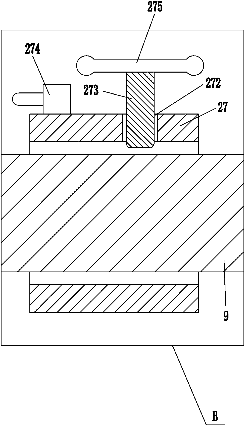
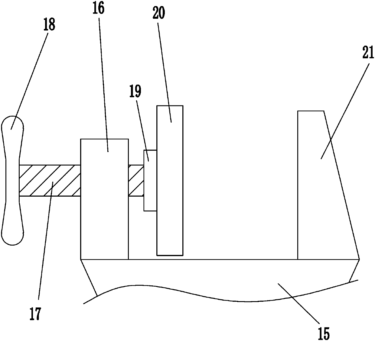
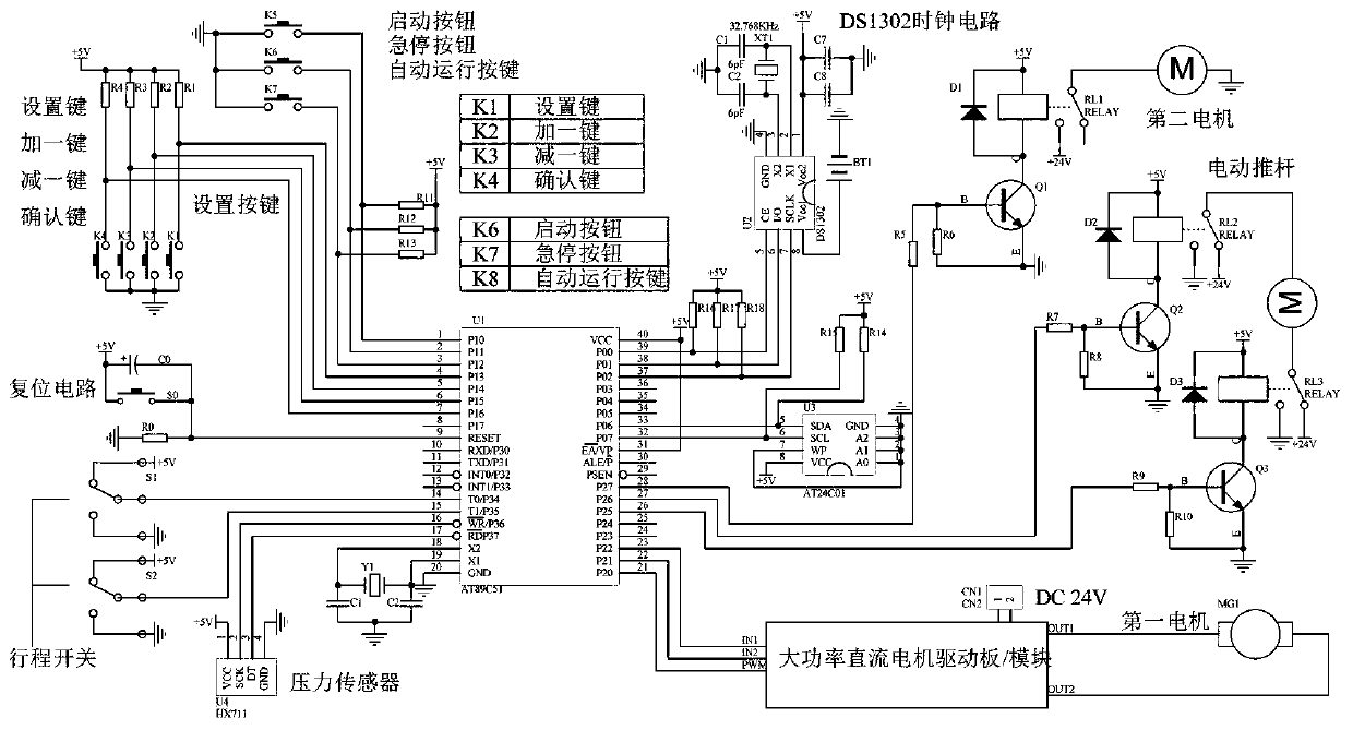
[0021] An automatic grinding machine for the surface of a polygonal metal plate, such as Figure 1-7 As shown, it includes a support seat 1, a first motor 2, a screw rod 3, a first nut 4, a mounting plate 5, a second motor 6, a grinding wheel 7, a bearing seat 8, a guide rod 9, a guide sleeve 10, a cantilever 11, Electric push rod 12, curved plate 13, rolling ball 14, mounting block 15, second nut 16, second screw rod 17, handle 18, first bushing 19, pressure plate 20, baffle plate 21, fixing mechanism 22, control Box 30, start button 31, emergency stop button 32, left shift button 33, right shift button 34, down button 35 and up button 36, the first motor 2 is installed on the upper left side of the front side of the support base 1, and the support base 1 is connected by bolts It is connected with the first motor 2 in the same way, bearing housings 8 are installed on the left and right sides of the upper front side of the support base 1, and a screw rod 3 is installed between...

Embodiment 2

[0023] An automatic grinding machine for the surface of a polygonal metal plate, such as Figure 1-7As shown, it includes a support seat 1, a first motor 2, a screw rod 3, a first nut 4, a mounting plate 5, a second motor 6, a grinding wheel 7, a bearing seat 8, a guide rod 9, a guide sleeve 10, a cantilever 11, Electric push rod 12, curved plate 13, rolling ball 14, mounting block 15, second nut 16, second screw rod 17, handle 18, first bushing 19, pressure plate 20, baffle plate 21, fixing mechanism 22, control Box 30, start button 31, emergency stop button 32, left shift button 33, right shift button 34, down button 35 and up button 36, the first motor 2 is installed on the upper left side of the front side of the support base 1, the upper part of the front side of the support base 1 Bearing housings 8 are installed on the left and right sides of the bearing housing 8, and a screw mandrel 3 is installed between the two bearing housings 8. The left end of the screw mandrel 3...

Embodiment 3

[0026] An automatic grinding machine for the surface of a polygonal metal plate, such as Figure 1-7 As shown, it includes a support seat 1, a first motor 2, a screw rod 3, a first nut 4, a mounting plate 5, a second motor 6, a grinding wheel 7, a bearing seat 8, a guide rod 9, a guide sleeve 10, a cantilever 11, Electric push rod 12, curved plate 13, rolling ball 14, mounting block 15, second nut 16, second screw rod 17, handle 18, first bushing 19, pressure plate 20, baffle plate 21, fixing mechanism 22, control Box 30, start button 31, emergency stop button 32, left shift button 33, right shift button 34, down button 35 and up button 36, the first motor 2 is installed on the upper left side of the front side of the support base 1, the upper part of the front side of the support base 1 Bearing housings 8 are installed on the left and right sides of the bearing housing 8, and a screw mandrel 3 is installed between the two bearing housings 8. The left end of the screw mandrel ...


PUM


Abstract

The invention relates to an automatic grinding machine, in particular to an automatic grinding machine for the surface of a polygonal metal plate. The automatic grinding machine for the surface of thepolygonal metal plate aims to achieve the technical effects that workers can be more relaxed, and time can be saved. According to the technical embodiment scheme, the automatic grinding machine for the surface of the polygonal metal plate comprises a supporting seat, a first motor, a screw rod, a first nut, a mounting plate, a second motor, a grinding wheel, a bearing block, a guide rod and the like, wherein a first motor is arranged on the upper left part of the front side of the supporting seat. According to the automatic grinding machine for the surface of the polygonal metal plate, a control module can control the first motor to rotate clockwise to drive the grinding wheel to move rightwards to grind the surface of the polygonal metal plate so that the surface of the polygonal metal plate can be automatically polished, then the workers can be more relaxed and can quickly grind the surface of the polygonal metal plate, and then the time can be saved; and the manual operation can bereduced through the action of a travel switch, so that the operation is simpler.

Description

technical field [0001] The invention relates to an automatic grinding machine, in particular to an automatic grinding machine for the surface of a polygonal metal plate. Background technique [0002] The polygonal metal plate is a common metal material. In order to better use the polygonal metal plate, the surface of the polygonal metal plate needs to be polished. Now the staff generally hold the polygonal metal plate with one hand and hold the grinding machine with the other hand to grind the polygonal metal plate. The surface is polished, but the grinding machine will generate a large vibration when it is working, which will cause the staff to be tired and take more time. Therefore, multiple staff are required to help polish the polygonal metal plate together, which is more labor-intensive. Contents of the invention [0003] In order to overcome the shortcomings that the staff are tired and need more time to grind the surface of the polygonal metal plate with a grinding ...

Claims


Application Information

Patent Timeline
Patent Type & Authority Applications(China)
IPC IPC(8): B24B41/00B24B47/04B24B55/00B24B27/00B24B47/12B24B7/10B24B41/02B24B49/16
CPCB24B7/10B24B27/0015B24B41/007B24B41/02B24B47/04B24B47/12B24B49/16B24B55/00
Inventor 马献恩
Owner TIANCHUANG ZHIKU CULTURE PROPAGATION SUZHOU CO LTD
Why Eureka
Try Eureka