
Electronic rear-view mirror with 360-degree panorama monitoring function

An electronic rearview mirror and functional technology, applied in vehicle parts, optical observation devices, transportation and packaging, etc., can solve the problems of limited visibility, inability to effectively reduce accidents, and driver distraction.

Inactive Publication Date: 2019-10-29
大吉国际有限公司
View PDF5 Cites 0 Cited by
  • Summary
  • Abstract
  • Description
  • Claims
  • Application Information

AI Technical Summary

Problems solved by technology

[0002] In the process of driving, the driver uses the rearview mirror to check the left, right and rear vehicle or pedestrian conditions, but because the rearview mirror has its dead angle, when someone, object or vehicle is located in the dead angle, the driver will Unknown, resulting in a higher chance of accidents
[0003] Therefore, in recent years, the technology of photographic equipment used for vehicle driving assistance has been vigorously developed, but most of them only passively provide images around the vehicle to assist the driver to avoid accidents, and if it is for driving safety, it needs to be used on the left and right. and rear blind spots to reduce the probability of accidents by eliminating dead spots around the vehicle as much as possible, but the visual range is still limited, and if you want to operate the function of switching lenses to display different images will also cause Diminished concentration while driving
In addition, most of the images shot by auxiliary photographic equipment are played on the computer screen in the car. If the driver needs to observe the image, he needs to shift his line of sight to the lower right, which is not safe in terms of driving safety. Therefore, it is still impossible to effectively reduce the possibility of accidents
[0004] Although there are driving assistance systems combined with 3D imaging technology today, it is not enough if the driver can only rely on the virtual image model to know the surrounding conditions of the vehicle, and if the system is damaged, the driver cannot know the surrounding conditions through the image. When the above two situations occur, the driver must adjust the display mode back to the actual shooting mode. In addition to the aforementioned problems, the action of adjusting the mode will also distract the driver, thereby increasing the danger of driving.

Method used


Image

  • Electronic rear-view mirror with 360-degree panorama monitoring function
  • Electronic rear-view mirror with 360-degree panorama monitoring function
  • Electronic rear-view mirror with 360-degree panorama monitoring function

Examples


Embodiment Construction

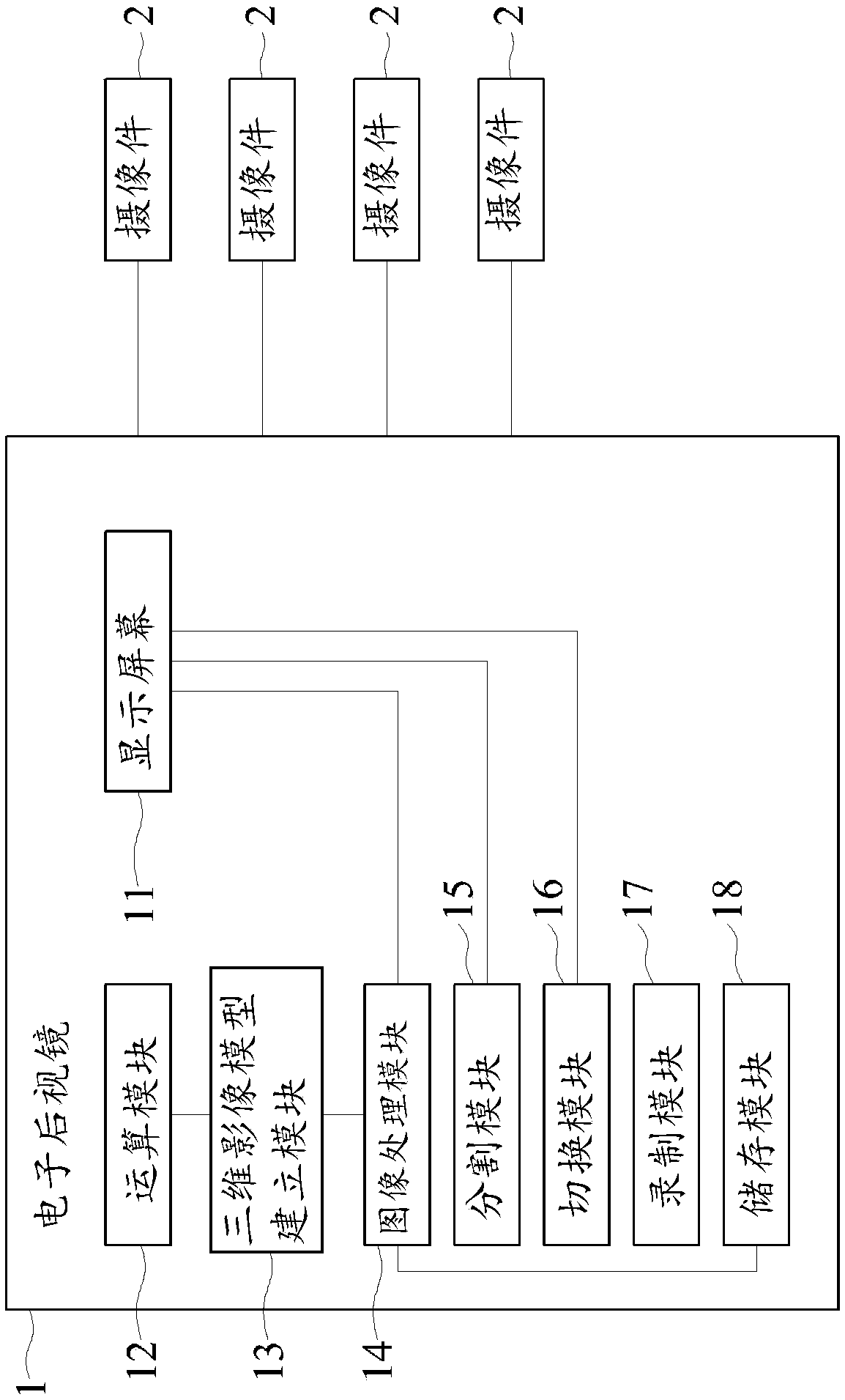
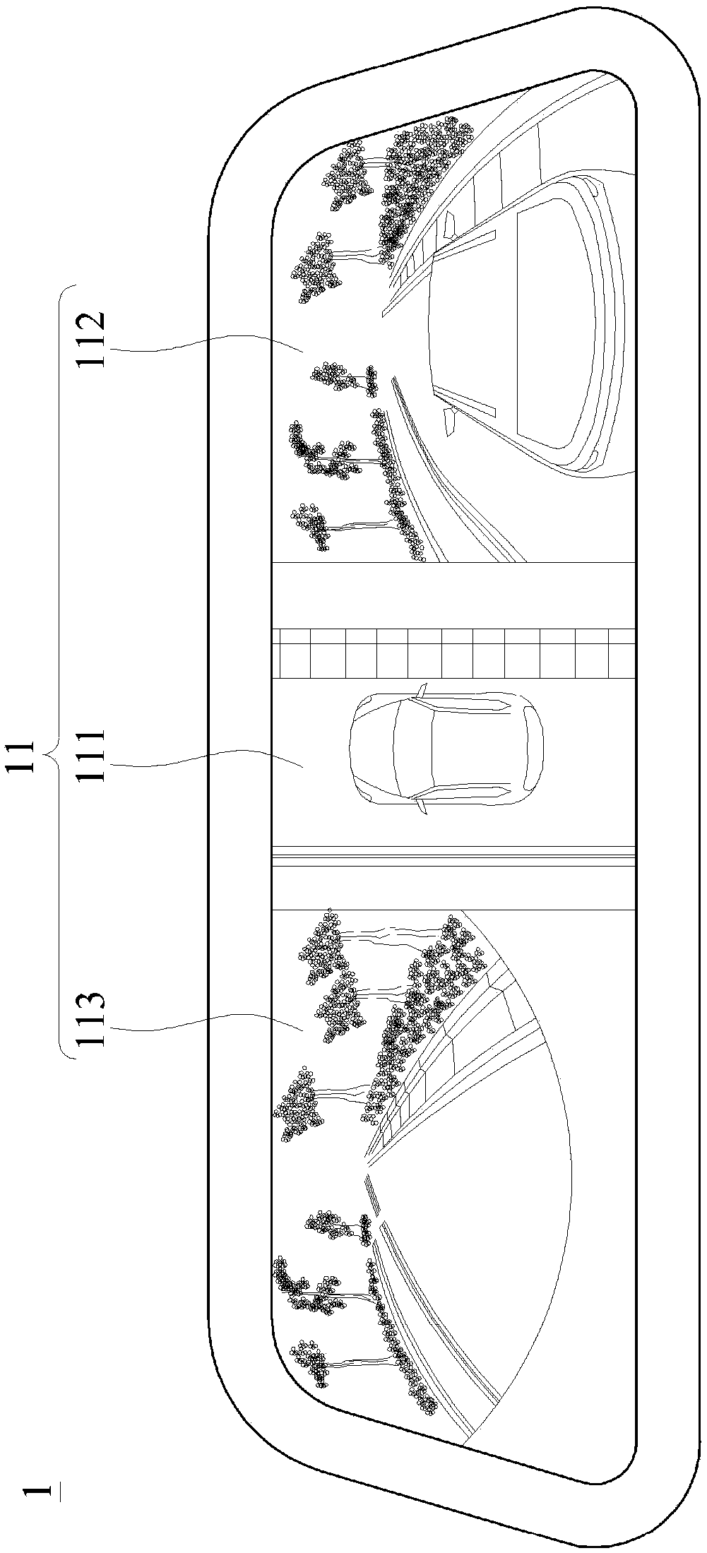
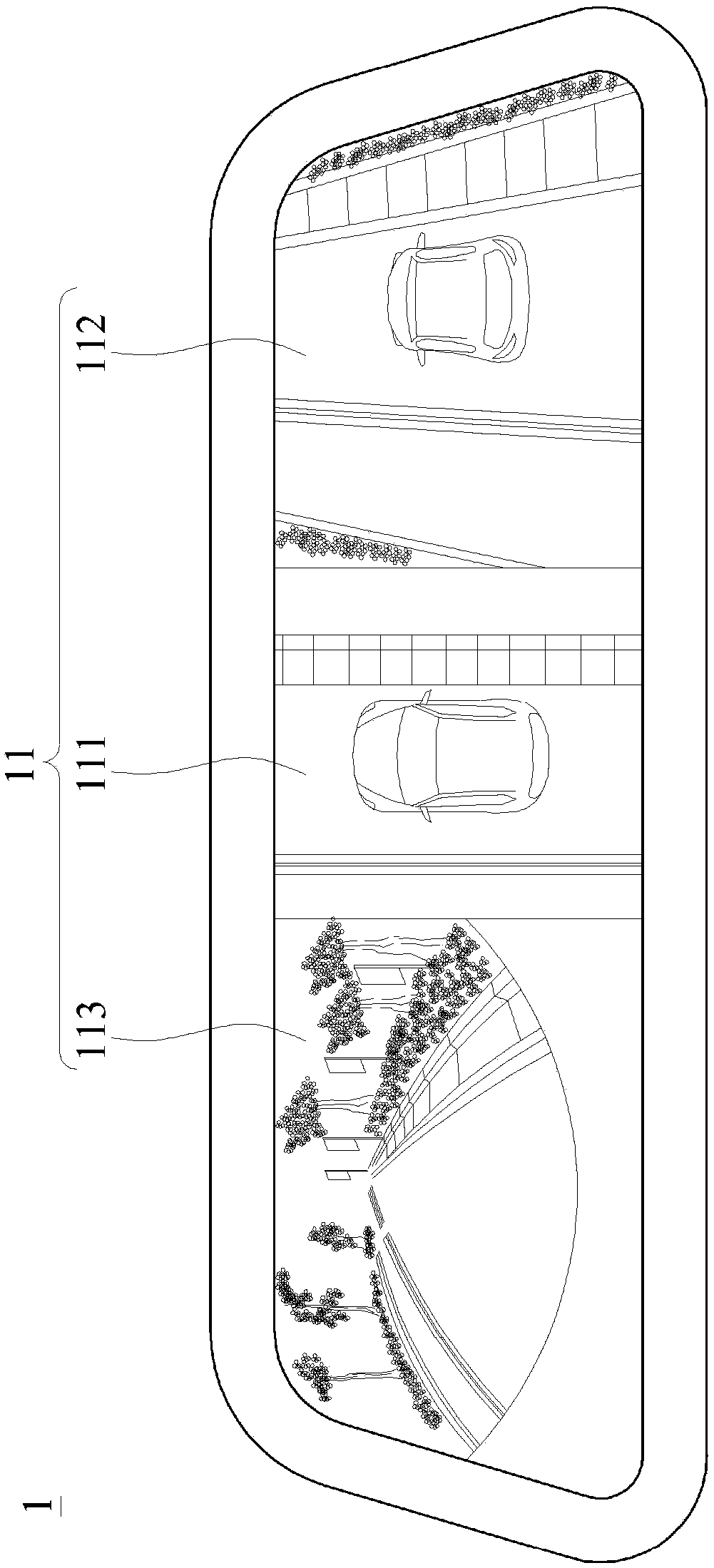
[0025] see Figure 1 to Figure 5 , which is a block diagram of a preferred embodiment of the present invention and a schematic diagram of a display screen when driving in different directions. As shown in the figure, in this embodiment, the electronic rearview mirror 1 with a 360-degree surrounding view monitoring function provided by the present invention is installed in the car and is electrically connected to a plurality of imaging devices 2, and the plurality of imaging devices Parts 2 are respectively arranged on the outer surfaces of the left, right, front and rear of the car body. The electronic rearview mirror 1 includes: a display screen 11, a computing module 12, a three-dimensional image model building module 13, an image processing module 14, A dividing module 15 , a switching module 16 , a recording module 17 and a storage module 18 .

[0026] The calculation module 12 is electrically connected to the multiple cameras 2 to receive images captured by the multiple ...


PUM


Abstract

The invention provides an electronic rear-view mirror with a 360-degree panorama monitoring function. The electronic rear-view mirror is arranged in a vehicle and electrically connected with multiplecamera shooting parts, and the camera shooting parts are arranged on the outer surfaces of the left, right, front and rear portions of a vehicle body respectively. The electronic rear-view mirror comprises a display screen, an operation module, a three-dimensional image model establishment module, an image processing module and a cutting module. In this way, when the electronic rear-view mirror plays an image, the situation can be avoided that the sight of a driver needs to be moved downwards when the driver watches the image, by making a three-dimensional image model, the driver can determinethe surrounding condition of the vehicle body in a non-sight-dead-corner mode, through the display screen, multiple played real-time images and virtual images are determined, and accordingly the driver can determine the accuracy of model establishment and make judgement suitable for the current situation by synthesizing different kinds of images.

Description

technical field [0001] The invention relates to the technical field of electronic rearview mirrors, especially a method that allows the driver to observe the surroundings of the vehicle without any blind spots while driving, and allows the driver to observe the actual and simulated images at the same time to make a more suitable mirror for the current situation. The electronic rearview mirror with 360-degree surround view monitoring function for judging the situation. Background technique [0002] In the process of driving, the driver uses the rearview mirror to detect the conditions of vehicles or pedestrians on the left, right and rear, but because the rearview mirror has its dead angle, when someone, object or vehicle is located in the blind angle, the driver will There is no way to know, leading to a higher probability of accidents. [0003] Therefore, in recent years, the technology of photographic equipment used for vehicle driving assistance has been vigorously devel...

Claims


Application Information

Patent Timeline
IPC IPC(8): B60R1/00B60R1/12
CPCB60R1/00B60R1/12B60R2001/1215B60R2300/105B60R2300/802
Inventor 李冠廷
Owner 大吉国际有限公司
Learn More