
Sensor for bionic skin, coil array, positioning method and touch collector

A sensor and inductance coil technology, applied in the field of bionic skin, can solve the problem of artificial skin being unable to be spliced ​​and flexible, and achieve the effect of facilitating bending deformation and splicing, preventing short circuit and damage, and being easy to achieve.

Active Publication Date: 2019-10-29
任干支
View PDF13 Cites 0 Cited by
  • Summary
  • Abstract
  • Description
  • Claims
  • Application Information

AI Technical Summary

Problems solved by technology

The invention comprehensively considers the texture and biological characteristics of the skin, and solves the problems of artificial skin that cannot be spliced ​​and flexibility. At the same time, it adopts an active method to sense pressure, frequency and even temperature, and will not cause short circuit due to unevenness and bending of the body surface. The active way is to generate self-inductance current through the inductance coil

Method used


Image

  • Sensor for bionic skin, coil array, positioning method and touch collector
  • Sensor for bionic skin, coil array, positioning method and touch collector
  • Sensor for bionic skin, coil array, positioning method and touch collector

Examples


Embodiment 1

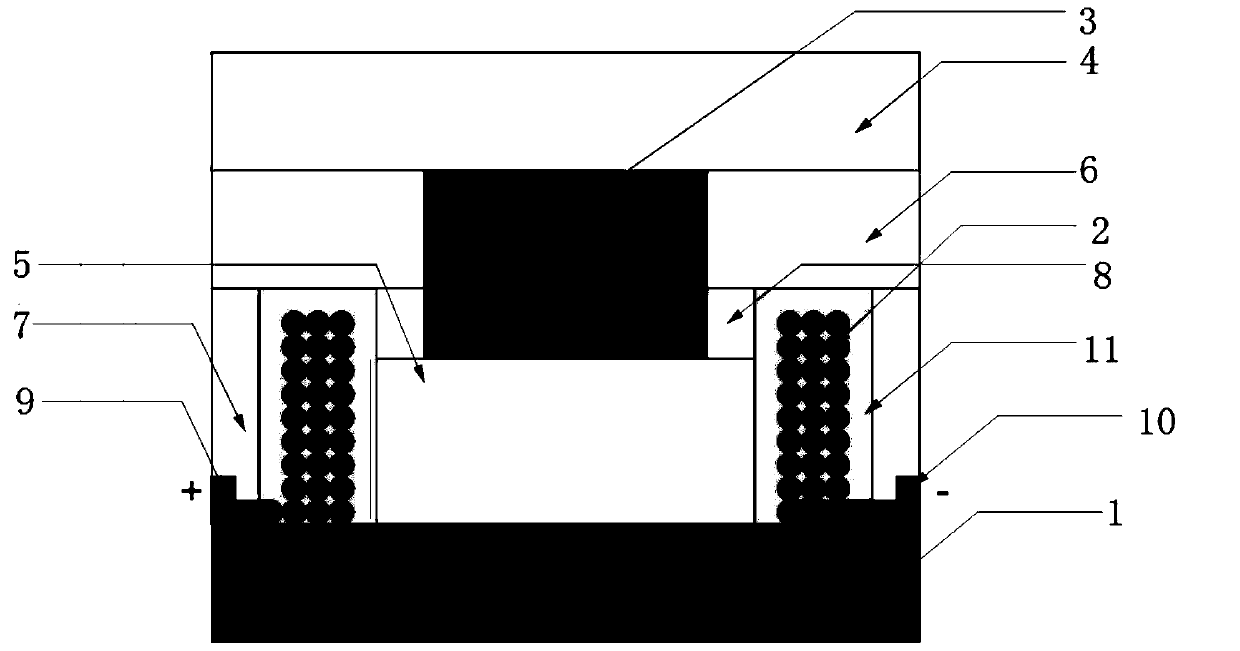
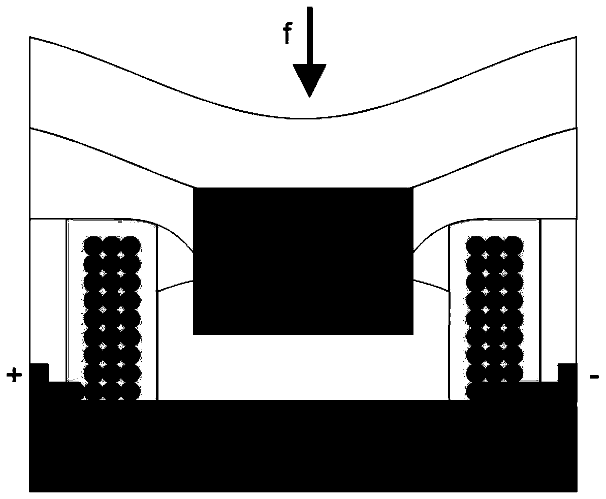
[0041] Such as figure 1 , figure 2As shown, a sensor for bionic skin includes a flexible base 1, which is square in shape, and also includes a coil structure 2, a magnetic core 3 and an upper plate 4, and the flexible base 1 is fixed with a hard insulating glue. Coil structure 2, the shape of the coil structure 2 is a ring body, the coil structure 2 is horizontally pasted on the flexible substrate 1, and the outside of the coil structure 2 is wrapped by a hard insulating glue 11; one end of the coil structure 2 is used as Positive pole 9, the other end as negative pole 10;

[0042] The magnetic core 3 partially penetrates the coil structure 2, and a first soft filling structure 5 is arranged between the bottom of the magnetic core 3 and the flexible substrate 1, and the part of the magnetic core 3 and the peripheral coil structure penetrated 2 non-contact, magnetic core 3 shape cylinder;

[0043] The magnetic core 3 is provided with a square upper plate 4, the upper plate ...

Embodiment 2

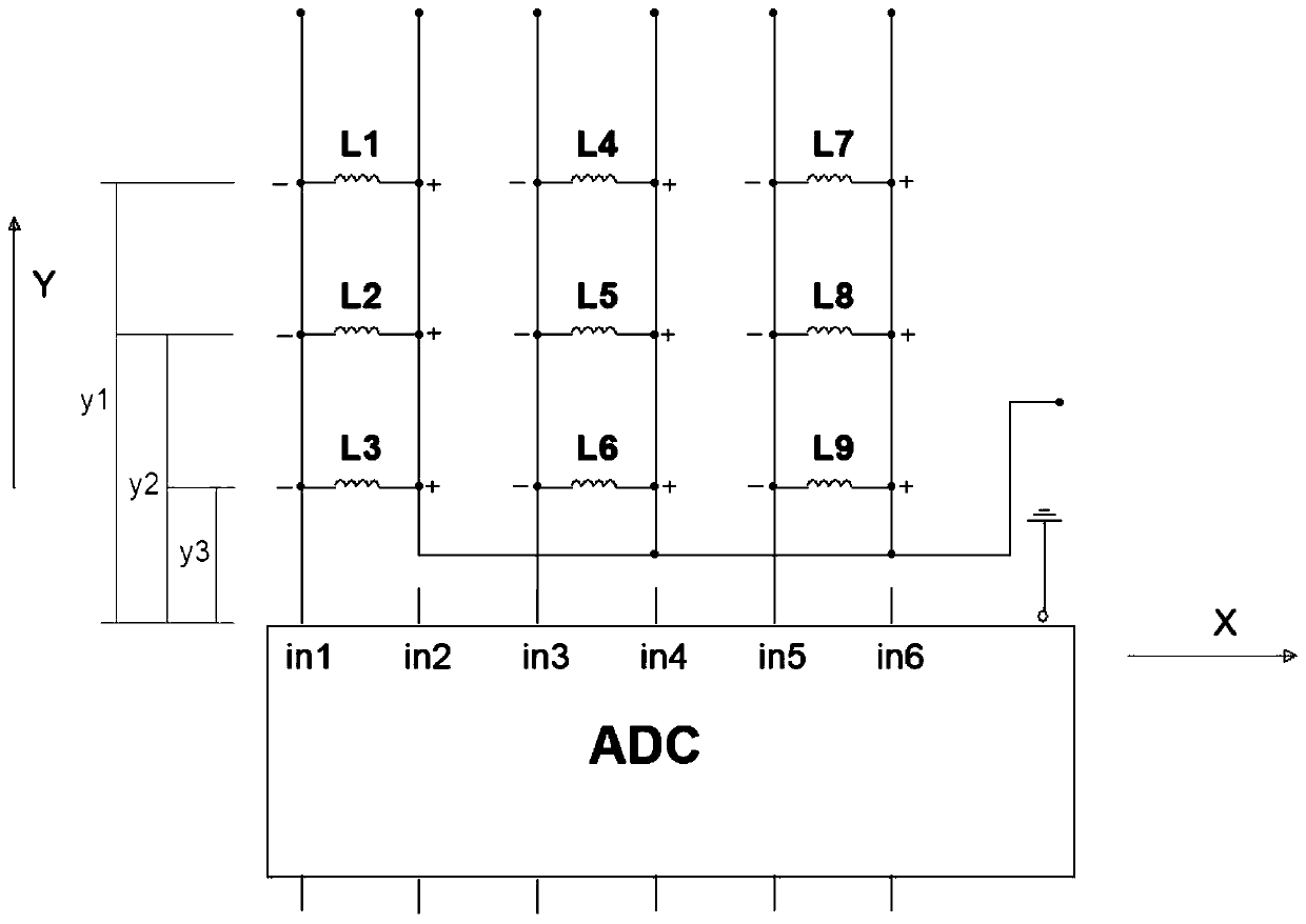
[0056] Such as Figure 1 to Figure 3 As shown, the difference between this embodiment and Embodiment 1 is that an inductive coil array structure for bionic skin includes ADC analog-to-digital conversion circuits and multiple sets of magnetoelectric sensors, and each set of magnetoelectric sensors is connected in parallel To each input terminal of the ADC analog-to-digital conversion circuit, and the distance between each group of magnetoelectric sensors is equal; each group of magnetoelectric sensors includes a plurality of magnetoelectric sensors, and a plurality of magnetoelectric sensors in the group are connected in parallel to the corresponding in the same loop.

[0057] The magnetoelectric sensor adopts a bionic skin sensor described in Example 1.

[0058] In this embodiment, three groups of magnetoelectric sensors are used for description, and each group of magnetoelectric sensors has three inductance coils. In this embodiment, a coil array circuit composed of a total ...

Embodiment 3

[0061] Such as figure 1 , figure 2 , Figure 4 As shown, the difference between this embodiment and Embodiment 2 is that each group of magnetoelectric sensors is connected in parallel to each input end of the ADC analog-to-digital conversion circuit in a specific form such as Figure 4 The connection form shown: the positive and negative poles of the coil loop array of each group of magnetoelectric sensors are connected to different input port pins of the ADC analog-to-digital conversion circuit.


PUM


Abstract

The invention discloses a sensor for bionic skin, a coil array, a positioning method and a touch collector. An inductance coil array structure for the bionic skin comprises an ADC analog-to-digital conversion circuit and multiple groups of magnetoelectric sensors; each group of magnetoelectric sensors are correspondingly accessed to various input ends of the ADC analog-to-digital conversion circuits in a parallel way, and the distance between each group of magnetoelectric sensors is equal; each group of magnetoelectric sensors comprise multiple magnetoelectric sensors, and multiple magnetoelectric sensors in the group are connected into the same corresponding loop in parallel; the magnetoelectric sensor adopts the sensor for the bionic skin disclosed by the invention; furthermore, the expansion splicing can be performed on the basis of a contact point occurrence location positioning method for bionic skin, various magnetoelectric sensor parallel loops in each group can perform parallelconnection extension to the Y axle; and the splicing of the whole positioning circuit on the plane is realized by extending the parallel loop on the x axle by adding the input end connecting pin of the ADC analog-to-digital conversion circuit.

Description

technical field [0001] The invention relates to the technical field of bionic skin, in particular to a bionic skin sensor, a coil array, a positioning method and a tactile collector. Background technique [0002] The Subramanian Sundaram stretchable haptic glove at the MIT Computer Science and Artificial Intelligence Laboratory has 548 sensors and 64 conductive wire electrodes. The sensor array consists of a tension-sensitive film and a network of conductive threads. Every point of coincidence between the electrode and the membrane is sensitive to perpendicular force and registers the resistance through the membrane. [0003] Although the existing artificial skin uses sensors to locate the contact position, the cost is still high, and the accuracy of pressure, temperature and frequency changes is low. Most film products cannot be accurately positioned, and the scalability and splicing performance are poor. Printing or other rubber products are not soft enough to touch and ...

Claims


Application Information

Patent Timeline
Patent Type & Authority Applications(China)
IPC IPC(8): G01B7/004G01D5/12
CPCG01B7/004G01D5/12
Inventor 任干支范莹霞范铁任湫金
Owner 任干支
Learn More