Oil storage tank based on oil tanker

A technology for oil tankers and cabins, which is applied in the direction of hull bulkheads, hulls, and hull parts, etc. It can solve problems such as pollution, impact force of oil bulkheads, oil leakage, etc., and achieve high strength, strong impact resistance, and reasonable structure Effect

Active Publication Date: 2019-11-01
ZHEJIANG OCEAN UNIV
View PDF10 Cites 6 Cited by
  • Summary
  • Abstract
  • Description
  • Claims
  • Application Information

AI Technical Summary

Problems solved by technology

The oil is installed in each oil-tight oil tank, and the oil tanker uses oil pumps and oil pipelines to transport oil when loading and unloading oil, so it does not need lifting booms and cargo cranes, and there is no need for large cargo openings on the deck. The following problems exist when the ship is moving: First, when the cargo tank is loaded with oil, there is a huge safety hazard at the bottom of the oil tank under the action of internal and external pressure. When the oil tank breaks and leaks, the oil will directly leak out of the tank, causing serious pollution At the same time, the hole will further increase with the leakage; second, the ship will sway in multiple directions during navigation, which will cause the oil in the oil tank to slosh, which will affect the stability of the ship, and will also affect the stability of the oil tank. The wall produces a huge impact, causing damage to the local structure of the oil tank, resulting in oil leakage and polluting the environment

Method used


Image

  • Oil storage tank based on oil tanker
  • Oil storage tank based on oil tanker
  • Oil storage tank based on oil tanker

Examples


Embodiment Construction

[0028] The present invention will be further described below in conjunction with the accompanying drawings and specific embodiments.

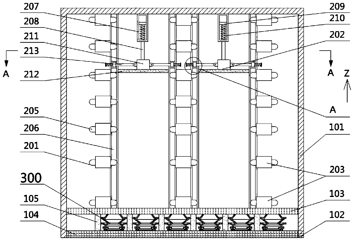
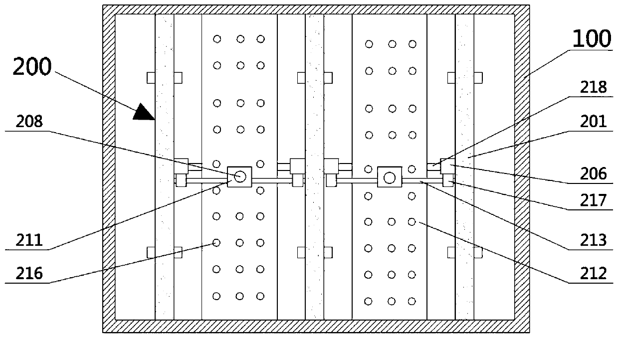
[0029] Such as figure 1 , Figure 5 As shown, an oil storage tank based on an oil tanker includes a cabin body 100, the cabin body 100 includes a bulkhead 101, and a base 102 installed at the bottom of the bulkhead 101, the base 102 includes an inner bottom plate 103, and the inner bottom plate 103 below Ship bottom plate 104, the upper end is installed on the inner bottom plate 103 and the lower end is installed on the ship bottom plate 104, a plurality of main ribs 105 distributed along the X direction, the upper end is installed on the inner bottom plate 103 and the lower end is installed on the ship bottom plate 104 distributed along the Y direction. The sub-floor 106, a plurality of reinforced areas 107 are formed between the main floor 105 and the sub-floor 106, which is characterized in that: the cabin body 100 is provided with a plural...


PUM


Abstract

The invention discloses an oil storage tank based on an oil tanker. The oil storage tank comprises a tank body, wherein the tank body comprises a tank wall and a base, the base is arranged at the bottom of the tank wall, a plurality of energy dissipation devices used for reducing the shaking amplitude of oil liquid are arranged in the tank body, an auxiliary structure used for improving the base strength and the ship stability is arranged in the base, the each energy dissipation device comprises a plurality of energy dissipation walls and energy dissipation components, the two ends of each energy dissipation wall are installed in the tank body, the energy dissipation walls are uniformly distributed in the x-direction, each energy dissipation component is movably installed on each energy dissipation wall and located between every two adjacent energy dissipation walls, the auxiliary structure comprises a toggle plate, a delay plate and a maintenance stabilization assembly, the upper endof the toggle plate is arranged in a reinforcing region through a supporting plate, the toggle plate is of a hollow circular truncated cone structure with a large upper part and a small lower part, one end of the delay plate is obliquely arranged on an inner bottom plate, the other end of the delay plate is obliquely arranged on the toggle plate, and the maintenance stabilization assembly is positioned under the toggle plate. According to the oil storage tank, the defects in the prior art are overcome, the oil storage tank is special for the oil tanker, and the oil storage tank is reasonable in structure, high in strength, high in impact resistance, safe and reliable.

Description

technical field [0001] The invention relates to the technical field of ships, in particular to an oil storage tank based on an oil tanker. Background technique [0002] With the development of the petrochemical industry, the transportation of raw products and refined oil tends to be specialized, and special crude oil carriers and refined oil tankers appear. Oil tankers, as they are usually called, mostly refer to ships that transport crude oil. Oil tankers are easily distinguished from general dry cargo ships in terms of appearance and layout. The oil pipeline and step bridge leading to the whole ship. The oil is installed in each oil-tight oil tank, and the oil tanker uses oil pumps and oil pipelines to transport oil when loading and unloading oil, so it does not need lifting booms and cargo cranes, and there is no need for large cargo openings on the deck. The following problems exist when the ship is moving: First, when the cargo tank is loaded with oil, there is a huge...

Claims


Application Information

Patent Timeline
IPC IPC(8): B63B3/56B63B25/12
CPCB63B3/56B63B25/12
Inventor 吴文锋张家阔卢金树张建伟邓佳佳魏东泽
Owner ZHEJIANG OCEAN UNIV
Why Eureka
Try Eureka