

Lifting type arch breaking device
A lifting and arch-breaking technology, applied in the directions of packaging, transportation, packaging, containers, etc., can solve the problems of low production efficiency and high potential safety hazards for manual dredging of material arches, and achieves the solution of material arching, high degree of automation and simple structure. Effect
- Summary
- Abstract
- Description
- Claims
- Application Information
AI Technical Summary
Problems solved by technology
Method used
Image

Examples
Embodiment 1
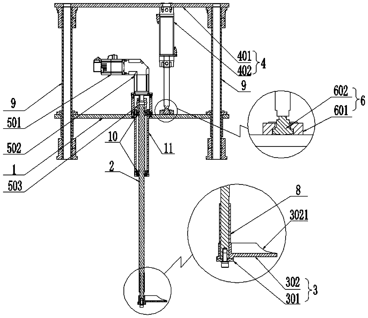
[0036] Such as Figure 1 ~ Figure 4 As shown, the lift-type arch breaking device of the present invention includes a support plate 1, a power device arranged on the support plate 1, a rotating shaft 2 and a stirring mechanism 3, and one end of the rotating shaft 2 passes through the support plate 1 and is connected to the power device. The other end is connected with the stirring mechanism 3, and the power device can drive the rotating shaft 2 to rotate relative to the support plate 1, and also includes a lifting mechanism 4 that can drive the support plate 1 to lift in the vertical direction; the power device includes a servo motor 501, Reducer 502 and shaft coupling 503, the servo motor 501 is connected to the rotating shaft 2 through the reducer 502 and shaft coupling 503 in turn; the lifting mechanism 4 includes a fixed plate arranged above the support plate 1 and parallel to the support plate 1 401 and the lifting cylinder 402 arranged on the fixed plate 401, the fixed en...
Embodiment 2
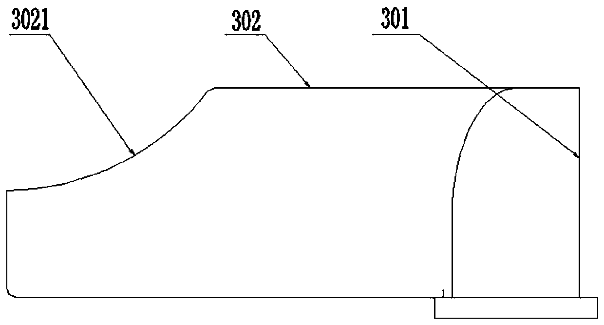
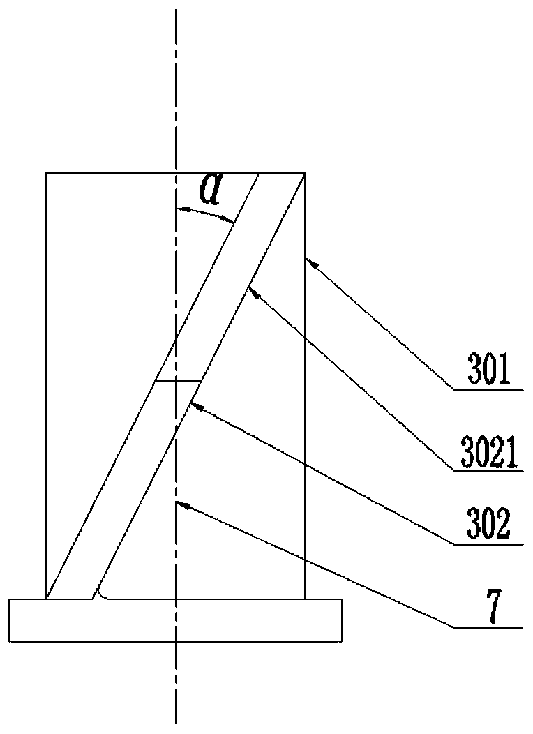
[0039] This embodiment is a further improvement made on the basis of the first embodiment, and an arc-shaped notch 3021 is provided on the upper part of the end of the blade 302 away from the mounting seat 301 . The lower end of the blade 302 is the arched material, and the upper end of the blade 302 is the arched material. The gap 3021 provided on the upper part of the blade 302 can reduce the contact area between the blade 302 and the arched material, thereby reducing the resistance of the blade 302 to run.
Embodiment 3
[0041]This embodiment is a further improvement made on the basis of Embodiment 1, and also includes a floating mechanism 6, the floating mechanism 6 includes a floating support 601 arranged on the support plate 1 and a floating support 601 arranged in the floating support 601 and The floating support 601 is loosely fitted with a floating joint 602 , and the movable end of the lifting cylinder 402 is connected to the support plate 1 through the floating joint 602 . There is a certain gap between the floating support 601 and the floating joint 602. The floating joint 602 can rotate in the floating support 601. When the installation of the fixed plate 401, the support plate 1 and the lifting cylinder 402 is uneven, there is a certain error or deviation. When the lifting cylinder 402 was shaking during operation, the floating mechanism 6 had an anti-swaying effect on the lifting cylinder, and could have a certain compensation effect on the error.
PUM
 Abstract
Description
Claims
Application Information