
A semiconductor electroplating clamping steel strip

A semiconductor and steel strip technology, applied in semiconductor devices, circuits, electrolytic components, etc., can solve problems such as waste of liquid medicine and poor conduction, and achieve the effects of stable current, avoiding contact, and stable and reliable connection

Active Publication Date: 2021-01-05
四川奥临科技有限公司
View PDF3 Cites 0 Cited by
  • Summary
  • Abstract
  • Description
  • Claims
  • Application Information

AI Technical Summary

Problems solved by technology

[0003] Aiming at the defects of poor electrical conduction and serious waste of liquid medicine in the prior art, the present invention discloses a clamping steel strip for semiconductor electroplating. Using the clamping steel strip described in the present invention can ensure that the current remains in a stable state during the electroplating process. Thereby avoiding and improving the quality of electroplating

Method used


Image

  • A semiconductor electroplating clamping steel strip
  • A semiconductor electroplating clamping steel strip
  • A semiconductor electroplating clamping steel strip

Examples


Embodiment approach 1

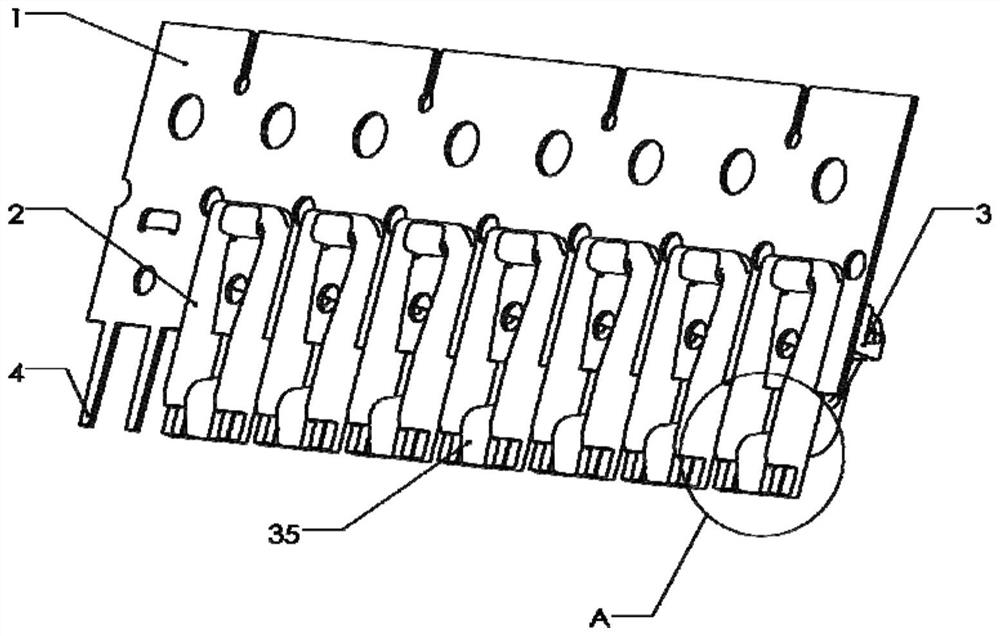
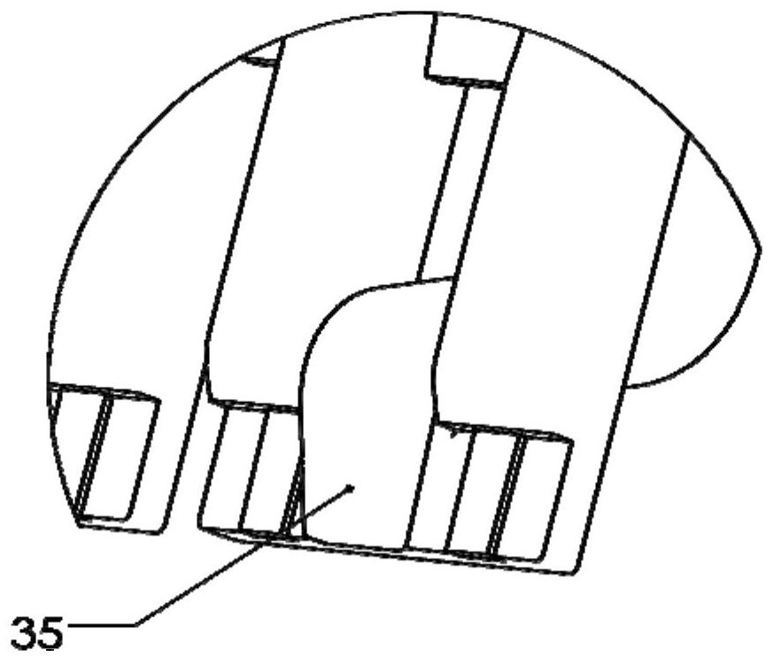
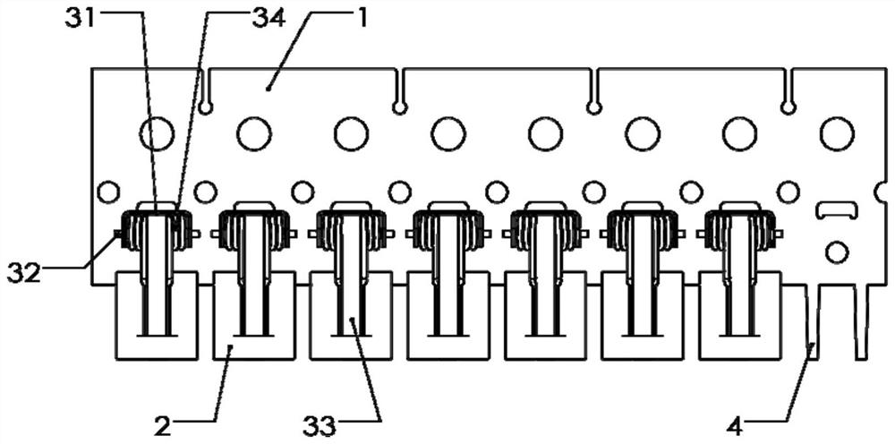
[0049] Such as Figure 1 to Figure 9 As shown, this embodiment is a basic embodiment of the present invention, which discloses a semiconductor electroplating clamping steel strip, the specific structure is as follows figure 1 , figure 2 and Figure 5 As shown, it includes a steel strip body 1, an insulating bracket 2 and a fixing clip 3, and the insulating bracket 2 is made of an insulating material resistant to electroplating liquid corrosion, such as engineering plastics; the steel strip body 1 is provided with a mounting hole, and the fixing clip The bottom of 3 is inserted into the mounting hole, thereby fixing the clip seat 31 on the steel strip body 1; the clip seat 31 is fixedly provided with a connecting shaft 32, and the middle part of the connecting shaft 32 is connected with a splint 33 through a rotating pair, and the splint The two sides of 33 are respectively connected with the inner side of the corresponding holder 31 by a torsion spring 34;

[0050] The ins...

Embodiment approach 2

[0052] Such as Figure 10 ~ Figure 18 As shown, this embodiment, as a preferred embodiment of the present invention, discloses a semiconductor electroplating clamping steel strip, its specific structure includes a steel strip body 1, an insulating support 2 and a fixing clip 3, and the fixing clip 3 Transformed by a torsion spring, a connecting rod 36 is provided in the middle of the fixing clip 3, and a mounting hole is provided on the steel belt body 1, and the connecting rod 36 is inserted into the mounting hole to fix the fixing clip; while the insulating bracket 2 One end of the steel belt body 1 is provided with a mounting groove 5 adapted to the steel strip body 1, and the opposite end of the mounting groove 5 is provided with a clamping surface 6; the insulating bracket 2 is also provided with a connecting hole, and the connecting hole can be provided with 2- 4, one end of the connecting hole communicates with the bottom surface of the installation groove 5, and the ou...


PUM

PropertyMeasurementUnit
lengthaaaaaaaaaa

Abstract

The invention discloses a semiconductor electroplating clamping steel strip. The semiconductor electroplating clamping steel strip comprises a steel strip body, the steel strip body is provided with an insulating support and a fixing clamp which are matched with each other, a clamping portion used for clamping a semiconductor is arranged between the insulating support and the fixing clamp in a matched mode; the steel strip body is further connected with a conducting strip, and the conducting strip penetrates through the insulating support, the circuit conduction is realized between the clamping part and the semiconductor. According to the semiconductor electroplating clamping steel strip, a semiconductor element to be electroplated and the steel strip body are directly conducted through the conducting strip, compared with the prior art, the circuit connection mode is simpler, so that the stability of the circuit is improved, and stable power supply in the electroplating process is ensured; meanwhile, the support of the insulation design can effectively reduce the consumption of electric quantity and electroplating water, and greatly reduces the production cost of the product.

Description

technical field [0001] The invention relates to the technical field of semiconductor electroplating equipment, in particular to a clamping steel strip for semiconductor electroplating. Background technique [0002] In the prior art, the production and packaging process of semiconductors includes the following steps: scribing, transferring, bonding, plastic packaging, deflashing, electroplating, printing, and rib cutting. During the electroplating process, the product needs to be clamped on a dedicated on the steel strip, and then immerse the product in the electroplating potion, and electroplate and tin-plate the product after the steel strip conducts electricity; The contact area between the parts and the steel strip body is mostly linear, and the contact area is small. After a long time of use, the clamping device of the clamping steel strip is prone to loosen, resulting in poor electrical conductivity, or even no electrical conductivity at all, which affects the electropl...

Claims


Application Information

Patent Timeline
Patent Type & Authority Patents(China)
IPC IPC(8): C25D17/08C25D17/00C25D7/12
CPCC25D7/12C25D17/007C25D17/08
Inventor 唐迪启陈军
Owner 四川奥临科技有限公司
Learn More