A buttress-type retaining wall with drainage function and its construction method

A buttress-type and retaining wall technology, which is applied in the field of buttress-type retaining walls and hydraulic factor-induced slope slope geological disaster prevention and control, can solve the problems of poor drainage performance, unfavorable upper soil drainage, and low drainage holes in the lower part, etc., to achieve Enhance the ability of anti-slip and anti-overturning, good drainage effect, flexible effect of retaining wall structure

Active Publication Date: 2020-09-08
HEBEI UNIV OF TECH
View PDF3 Cites 1 Cited by
  • Summary
  • Abstract
  • Description
  • Claims
  • Application Information

AI Technical Summary

Problems solved by technology

Although there are currently patents for retaining walls that improve drainage effects, they have defects such as cumbersome construction steps, limited height of the main body of the retaining wall, or poor drainage performance.
[0004] For example: the application number is 201620009591.3 "Geogrid Reinforced Buttress Retaining Wall". This patent has both drainage and anti-skid capabilities, and its construction steps are relatively simple, but the lower drainage holes are too low, which is not conducive to the upper soil. Drainage, in addition, the fill soil is located on the side of the buttress, and the strength performance of the main structure of the retaining wall cannot be fully exerted;
[0005] The application number is 201820901188.0 "A Retaining Wall". This patent considers the drainage effect, but the poor integrity of the retaining wall and the rear wall collection and drainage structure limits the anti-sliding support performance of the retaining wall structure, so that the height of the main wall structure of the retaining wall should not be too large
[0006] Similarly, the application number is 201420073853.3 "A Buttress-type Retaining Wall Structure Applicable to Deep and Soft Soil Foundation", which only adds drainage holes on the main wall surface, without considering the water collection and drainage function of the retaining body itself, and the drainage effect is not good. obvious

Method used


Image

  • A buttress-type retaining wall with drainage function and its construction method
  • A buttress-type retaining wall with drainage function and its construction method
  • A buttress-type retaining wall with drainage function and its construction method

Examples


Embodiment 1

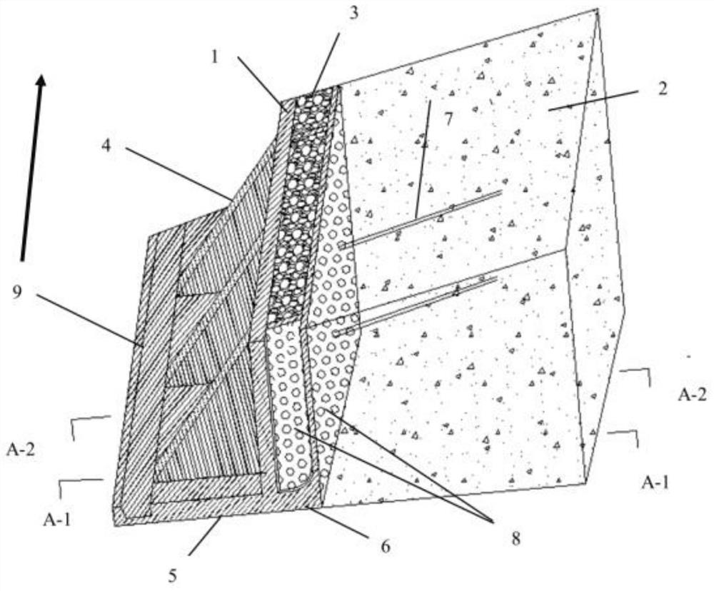
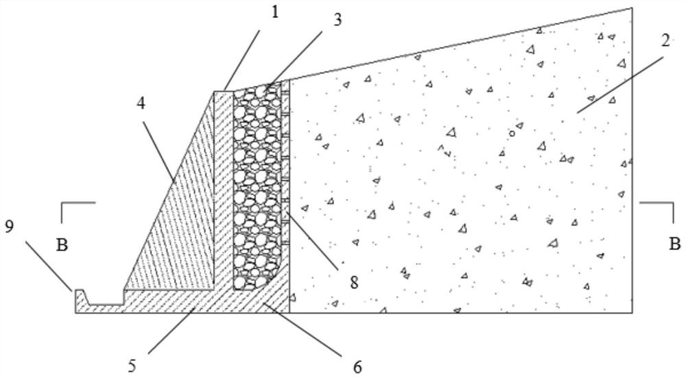
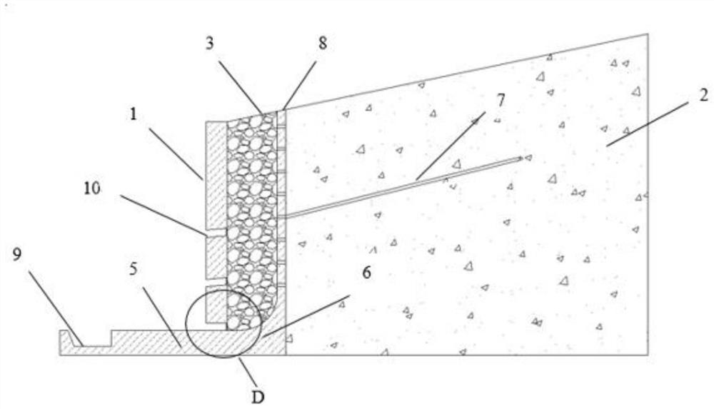
[0044] This embodiment discloses a buttress-type retaining wall with drainage function, including a main wall surface 1, a buttress 4, a wall heel board 5, a wall toe board 6, a water guide pipe 7, a water guide wall 8, a drainage ditch 9, a drainage hole 10;

[0045] refer to figure 1 , Figure 5, the side of the main wall 1 is provided with a retaining body 2, which is suitable for a relatively large height range, and should not exceed 15m, generally 6-12m, wherein the lower part of the main wall is provided with three rows of drainage through the retaining wall The hole 10 extends along the length of the retaining wall ( figure 1 The length of the construction section in the direction indicated by the middle arrow) shall not exceed 20m, and the width of the topmost wall of the main wall 1 shall not be less than 0.2m;

[0046] refer to figure 2 , Figure 4 , the buttress 4 is arranged on the other side of the main wall 1, and the thickness of the buttress is changed ac...

Embodiment 2

[0053] This embodiment discloses a construction method for the buttress-type retaining wall structure with drainage function described in Embodiment 1, which includes the following steps:

[0054] S1. According to the actual engineering needs and the principle of economical practicability, design and determine the parameters and dimensions of the buttress-type retaining wall (determine the height and width of the main wall, the size of the buttress, and the toe board according to the size of the retained soil body) , the size of the wall heel board), and complete the construction drawing; S2. Measurement and setting out: divide the construction section according to the construction drawing, and measure the subgrade centerline and foundation at the position of the wall toe board (the main wall surface, the wall toe board, and the wall heel board constitute Foundation) main axis, wall top (the wall top of the main wall) axis, retaining wall start and end point and cross section, ...

Embodiment 3

[0064] In the construction method of this embodiment, after step S2 in the implementation method of embodiment 2, the lower part of the retaining body is drilled, and the drilled holes are used to place the water pipe. Afterwards, steps S3-S8 are executed, and after the crushed stone and earthwork both reach the specified height, compaction is performed to complete the construction.

[0065] What is not mentioned in the present invention is applicable to the prior art.


PUM


Abstract

The invention relates to a counterfort retaining wall with a drainage function and a construction method thereof. The retaining wall belongs to the technical field of geological disaster prevention and control. The counterfort retaining wall comprises a main body wall surface, a gravel water-collecting trough, a drainage ditch, a water guiding pipe and a filter net. The gravel water-collecting trough filled with gravels is disposed between the main body wall surface and a retained soil body; the gravel water-collecting trough is defined by the main body wall surface, a water guiding wall and awall toe board; one end of the water guiding pipe is embedded into the retained soil body, and the other end of the water guiding pipe communicates with the gravel water-collecting trough; besides, drainage holes are formed in the main body wall surface, and the wall heel board is provided with the drainage ditch; and therefore a complete drainage system is formed. Underground water in the retained soil body enters the gravel water-collecting trough through the water guiding pipe and then is discharged through the drainage holes, and thus the influence, on the soil body stability, of the underground water can be reduced in time. Moreover the anti-capsizing and anti-slippage capacity of the wall can be improved through the weight of gravels which fill in the gravel water-collecting troughin rear of the main body wall surface.

Description

technical field [0001] The invention relates to a buttress-type retaining wall with drainage function, especially a drainage retaining wall structure adopted for landslide control, filling body reinforcement, slope reinforcement, etc. in areas with frequent rainfall, and belongs to the technical field of geological disaster prevention and control. Prevention and control of slope slope geological hazards induced by hydraulic factors such as rainfall. Background technique [0002] Hydraulic effects such as rainfall, melting ice and snow, and reservoir water ups and downs are one of the most important external factors that induce landslide disasters. The infiltration of surface water into the rock and soil mass will reduce the mechanical properties of the rock and soil mass, increase the seepage pressure in the slope, and cause erosion and erosion of the rock and soil mass in the slope. Therefore, strengthening drainage in the slope is the key to landslide disaster prevention a...

Claims


Application Information

Patent Timeline
Patent Type & Authority Patents(China)
IPC IPC(8): E02D17/20E02D29/02E03F5/00
CPCE02D17/20E02D29/02E03F5/00
Inventor 黄达袁宇吴礼舟王俊杰肖衡林裴向军
Owner HEBEI UNIV OF TECH
Why Eureka
Try Eureka