Welding heat circulation curve measuring instrument

A welding heat cycle and measuring instrument technology, applied in the field of mechanical processing, can solve the problems of plate waste, troublesome operation, heavy workload, etc., and achieve the effect of accurate measurement, small workload and simple operation

Active Publication Date: 2019-11-01
徐州新南湖科技有限公司
View PDF12 Cites 1 Cited by
  • Summary
  • Abstract
  • Description
  • Claims
  • Application Information

AI Technical Summary

Problems solved by technology

[0002] Welding, also known as welding and melting, is a manufacturing process and technology for joining metals or other thermoplastic materials such as plastics by means of heating, high temperature or high pressure. The welding thermal cycle curve refers to the time when the heat source moves along the weldment during the welding process. , the temperature of a certain point on the weldment goes from low to high, and after reaching the highest value, it shows the process curve of the temperature changing with time from high to low. The existing method of measuring its thermal cycle curve is mainly to put the thermocouple through the drill The hole is placed inside the welding plate to detect its temperature. This method often requires the welding plate to be drilled in advance. The workload is large, the operation is troublesome and the plate is wasted, and the thermocouple cannot be observed inside.
[0003] The notification number CN104267061A discloses a method and device for measuring the temperature curve of steel plate welding heat cycle, including the preparation of the test piece and the process of measuring the welding heat cycle. First, the steel plate to be tested is used to make a wedge plate and an arc strike plate; Weld the parts together, paste it on the specified position of the measuring surface of the wedge-shaped plate with high-temperature glue; fix the arc-starting plate and the wedge-shaped plate by electric welding, and perform welding on the welding surface from the arc-starting plate to the wedge-shaped plate according to the set welding specification parameters At the same time, the recorder is used to record the temperature change of each measurement position with time; according to the time-temperature data measured by the recorder, the welding heat cycle curves of different welding heat-affected zones are drawn. This invention needs to make wedge-shaped plates and arc strike plates in advance. The quantity is large, and at the same time, it is necessary to assemble and fix the arc strike plate and wedge plate, so that the two plates can be seamlessly combined during welding, and there is a lack of necessary auxiliary fixing devices
[0004] The notification number CN101639456A discloses a method and device for testing thermal cycle parameters of laser welding. First, a wedge-shaped bar is placed between two welding test plates, and the end face of the welding test plate corresponding to the slope of the wedge-shaped bar is used as a temperature measuring surface. A number of through holes for placing thermocouples are evenly distributed along the end surface of the welding test plate, and the thermocouples are arranged accordingly. The wedge-shaped strips are closely connected with the temperature measuring surface of the thermocouples; so far, the temperature measuring surface and the laser welding seam metal have a certain Then, starting from the bottom of the wedge-shaped strip as the welding start end, and the top of the wedge-shaped strip as the welding end, as the laser welding heat source moves, the uniformly implanted thermocouples can gradually approach the weld metal, thus obtaining For thermal cycle parameters at different positions on the vertical line from the weld, the device uses embedded thermocouples for temperature measurement, which requires drilling in advance, which is troublesome

Method used


Image

  • Welding heat circulation curve measuring instrument
  • Welding heat circulation curve measuring instrument
  • Welding heat circulation curve measuring instrument

Examples


Embodiment 2

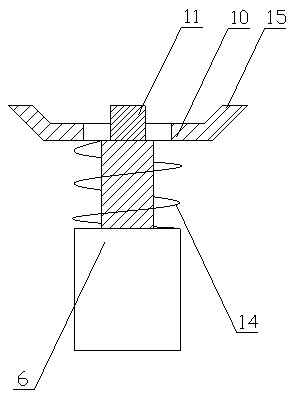
[0027] The difference between this embodiment and embodiment 1 is: the surface of the non-slip tooth (15) is provided with a heat-resistant pad (16); during use, due to the heat conduction temperature of the welding plate (2) during welding, the heat-resistant pad (16) ) It can protect the push plate (10) from damage;

Embodiment 3

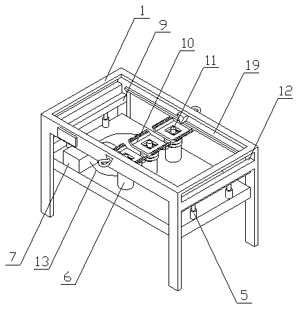
[0029] The difference between this embodiment and the first embodiment is that four secondary springs (17) are arranged on the plane of the pressing plate (10), and they are respectively located at four corner positions of the plane of the pressing plate (10); When in use, it can provide stronger support for the laminated push plate (10) and more stable support for the welding of the two welding plates (2);

Embodiment 4

[0031] The difference between this embodiment and embodiment 1 is: a set of suction cups (18) are respectively placed on both end faces of the laminated push plate (10), and a group of suction cups (18) is composed of two suction cups (18), and Close to the two ends of the push plate (10) respectively; when in use, the welding plate (2) can be effectively attached to prevent the phenomenon of not tightly attaching from affecting the measurement;

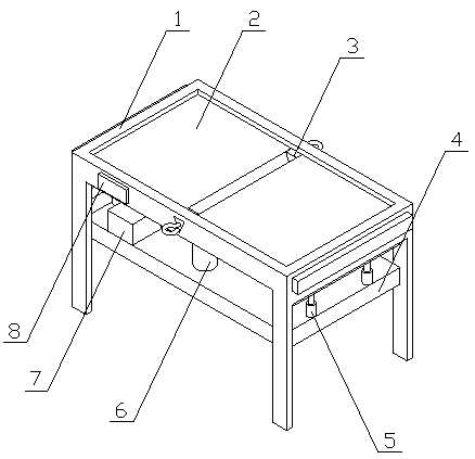
[0032] The thermocouple (11) can detect the temperature of the weld in real time, and transmit the detection signal to the data processor (7);

[0033] A computer program is stored in the data processor (7), and the following steps are implemented when the program is executed:

[0034] Receive the temperature signal transmitted by the thermocouple (11), and perform data processing to obtain the thermal cycle curve of the current welding process, and transmit it to the display (8);

[0035] The display (8) and the data processor (7) exchange ...


PUM


Abstract

A welding heat circulation curve measuring instrument of the invention discloses a measuring instrument that eliminates the need for drilling a hole to embed a thermocouple and is capable of effectively supporting two welding plates so that the welding plates can be reliably and effectively fixed to avoid the problem that the two welding plates are uneven after being welded. The welding heat circulation curve measuring instrument is characterized in that a supporting frame consists of a top box and four supporting rods, the supporting rods are vertically placed on four corners of the bottom ofthe top box at one end respectively, a supporting plate is placed below the top box, four corners of the supporting plate are separately connected to the four supporting rods, the supporting plate and the top box are parallel to each other, a straight slot is respectively formed on two ends of the top box, a sliding groove is respectively formed on two inner sides of the top box, two ends of thesliding grooves communicate the straight slots on two ends of the top box, multiple second cylinders are placed in the middle of the supporting plate in equal distances, and are distributed along a direction from one side to the other side of the top box, and a supporting spring is arranged on piston rods of the second cylinders in a sleeving manner.

Description

Technical field [0001] The invention relates to a welding thermal cycle curve measuring instrument, which relates to a measuring instrument for measuring the thermal cycle curve of a weldment during welding, and belongs to the field of mechanical processing. In particular, it relates to a measuring instrument which can effectively support and fix two welded plates without drilling and burying the thermocouple. Background technique [0002] Welding is also called welding and welding. It is a manufacturing process and technology for joining metals or other thermoplastic materials such as plastics by heating, high temperature or high pressure. The welding thermal cycle curve refers to the heat source moving along the weldment during the welding process. , The temperature of a certain point on the weldment changes from low to high, and after reaching the highest value, the process curve of this temperature change with time is displayed from high to low. The existing method of measuri...

Claims


Application Information

Patent Timeline
Patent Type & Authority Applications(China)
IPC IPC(8): G01N25/20
CPCG01N25/20
Inventor 不公告发明人
Owner 徐州新南湖科技有限公司
Why Eureka
Try Eureka