Novel aluminum-plastic composite belt longitudinal wrapping and releasing tension constant device
A technology of aluminum-plastic composite tape and vertical wrapping, which is applied in the manufacture of electrical components, circuits, cables/conductors, etc. It can solve problems such as warped angles and broken tapes, and achieve the effect of eliminating broken tapes and improving the appearance quality
- Summary
- Abstract
- Description
- Claims
- Application Information
AI Technical Summary
Problems solved by technology
Method used
Image

Examples
Embodiment Construction
[0020] The technical solution adopted by the present invention will be further described below in combination with schematic diagrams.
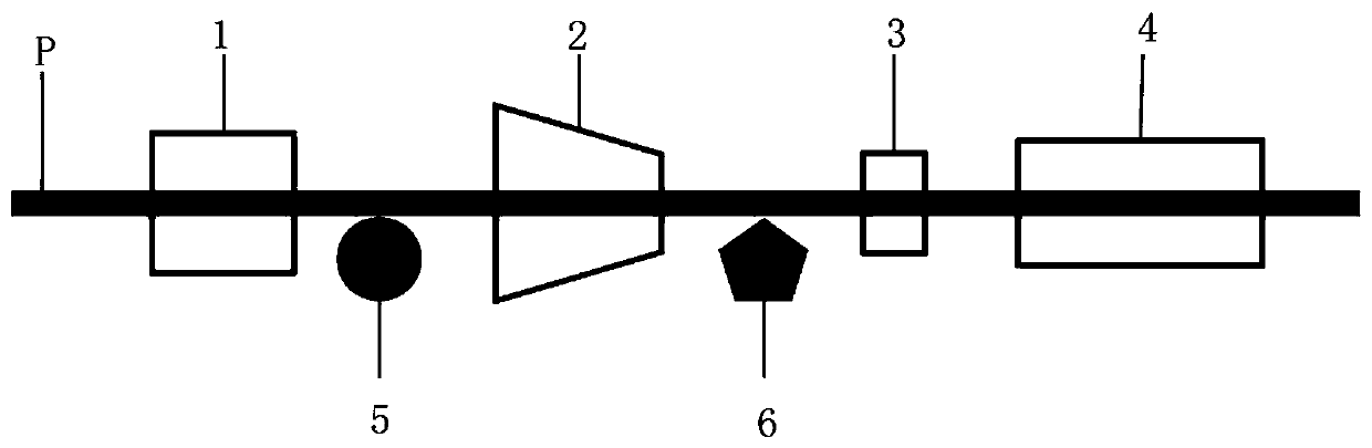
[0021] Such as figure 2 , a new type of constant tension device for longitudinal wrapping of aluminum-plastic composite tape, which includes a tape release frame 100, a pneumatic brake 101, a straightening roller assembly 104, and a tension sensor 105.
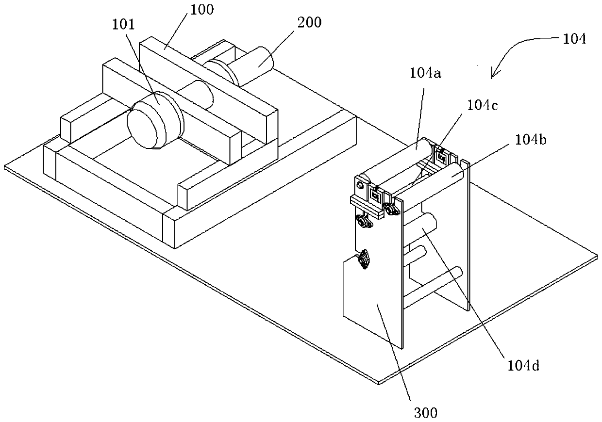
[0022] see image 3 , the tape rack 100 installs the aluminum-plastic composite tape roll through the release shaft 200 of the aluminum-plastic composite tape roll, image 3 Aluminum-plastic composite tape volume release shaft 200 is not installed with aluminum-plastic composite tape volume. The end of the tape roll protrudes from the bearing seat so as to install the corresponding brake assembly. A pneumatic brake 101 is installed at the release shaft of the aluminum-plastic composite tape of the tape rack, and the pneumatic brake 101 can brake the release shaft of the aluminum-plastic co...
PUM
 Abstract
Description
Claims
Application Information
 - R&D
- Intellectual Property
- Life Sciences
- Materials
- Tech Scout
- Unparalleled Data Quality
- Higher Quality Content
- 60% Fewer Hallucinations
Browse by: Latest US Patents, China's latest patents, Technical Efficacy Thesaurus, Application Domain, Technology Topic, Popular Technical Reports.
© 2025 PatSnap. All rights reserved.Legal|Privacy policy|Modern Slavery Act Transparency Statement|Sitemap|About US| Contact US: help@patsnap.com