redox flow battery

A technology for flow batteries and battery modules, applied in the direction of regenerative fuel cells, etc., can solve the problems of uneven performance of battery cells, increase fluid flow resistance, component damage, etc., to reduce or shunt current, eliminate shunt current, and improve The effect of efficiency

Active Publication Date: 2022-07-12
STANDARD ENERGY CO LTD
View PDF4 Cites 0 Cited by
  • Summary
  • Abstract
  • Description
  • Claims
  • Application Information

AI Technical Summary

Problems solved by technology

However, the electrolyte filled with the manifold functions as an electrical path connecting each battery unit, so it can become a moving path for electrons. Through such a path, a shunt current (shunt current) will be generated, and a part of the energy will be lost during charging and discharging. Loss due to shunt current, which can be a major cause of efficiency loss, component damage, and uneven cell performance
In the past, in order to reduce such shunt current, the method of increasing the length of the manifold and reducing the cross-sectional area was mainly used. However, this increases the flow resistance of the fluid and causes suction loss. Therefore, it is required to establish a countermeasure to overcome this situation.

Method used


Image

  • redox flow battery
  • redox flow battery
  • redox flow battery

Examples


Embodiment Construction

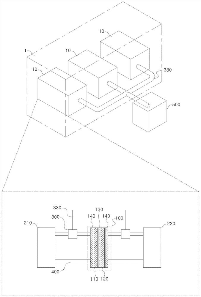
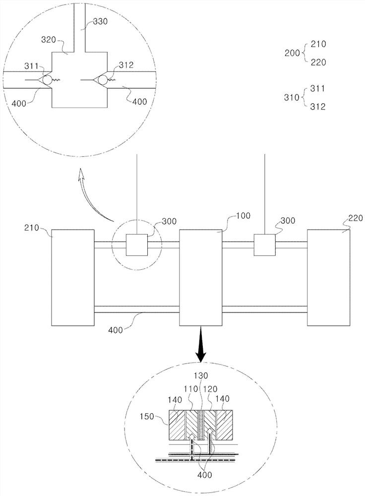
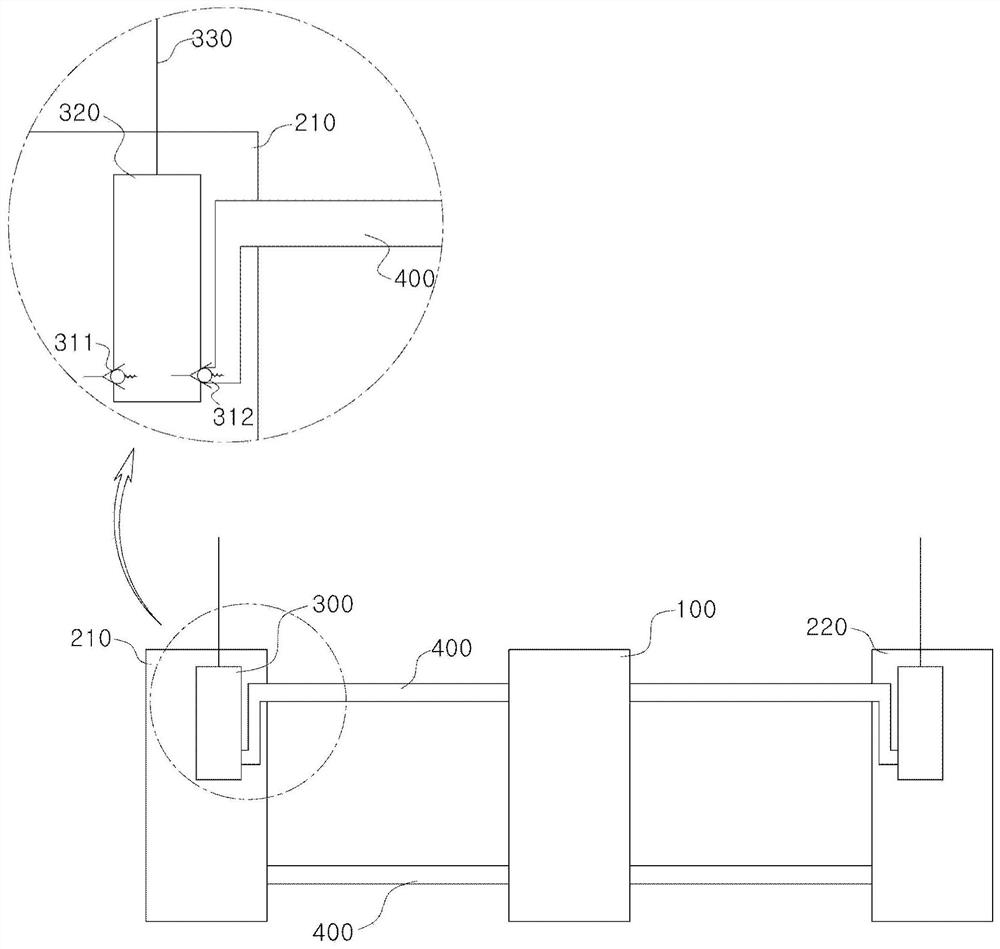
[0049] Hereinafter, the redox flow battery according to the present invention will be described in detail with reference to specific examples. The specific examples described below are provided as examples in order to sufficiently convey the idea of ​​the present invention to those skilled in the art.

[0050] Therefore, the present invention is not limited to the specific examples shown below, and can be embodied in other forms. The specific examples shown below are described only for clarifying the idea of ​​the present invention, and the present invention is not limited thereto.

[0051] At this time, the technical terms and scientific terms used have the meanings commonly understood by those skilled in the art unless otherwise defined, and well-known functions that may unnecessarily obscure the gist of the present invention are omitted in the following description. and a description of the structure.

[0052] In addition, the accompanying drawings described below are prov...


PUM


Abstract

The redox flow battery according to the present invention includes a battery cell or a stack and an electrolyte tank in a battery module, and applies a pump-replacing device for conveying the electrolyte to the battery cell or stack for each battery module. The generation of shunt current can be reduced in an epoch-making manner. In addition, by providing an electrolyte solution tank for each battery module, the transfer route of the electrolyte solution can be drastically reduced, and in order to transport the electrolyte solution, a fluid control unit using pressure is provided for each module instead of a pump, so that it is possible to Saves the power required for pump drive and can improve the efficiency of the battery.

Description

technical field [0001] The present invention relates to a redox flow battery, and in particular, to a redox flow battery as follows, characterized in that a plurality of battery modules are combined, and in the battery module, each battery cell is provided with The electrolytic solution tank for storing the catholyte solution and the fluid control unit for transferring the electrolytic solution from the electrolytic solution tank to the battery cells can shorten the reaction time, improve the efficiency, and suppress the shunt current. produce. Background technique [0002] In recent years, renewable energy sources such as solar energy and wind energy have been favored as methods for suppressing emissions of greenhouse gases, which are a major cause of global warming, and various studies are being conducted for their practical spread. However, renewable energy is greatly affected by the site selection environment and natural conditions. Furthermore, since the output of reg...

Claims


Application Information

Patent Timeline
Patent Type & Authority Patents(China)
IPC IPC(8): H01M8/18
CPCH01M8/18Y02E60/50
Inventor 金富基金箕贤赵范熙崔淡潭
Owner STANDARD ENERGY CO LTD
Why Eureka
Try Eureka