Automatic adjustment structure and method of cutter position of gear shaper

A technology of automatic adjustment and gear shaper, applied in the direction of gear cutting machine, gear teeth, mechanical equipment, etc., can solve the problems of increasing worker safety risk, reducing production efficiency, inconvenient operation, etc., to eliminate the risk of tool hitting the workpiece and reduce labor. Strength, easy to manufacture and assemble

Pending Publication Date: 2019-11-05
宜昌长机科技有限责任公司
View PDF0 Cites 3 Cited by
  • Summary
  • Abstract
  • Description
  • Claims
  • Application Information

AI Technical Summary

Problems solved by technology

[0003] 1. The operation is inconvenient. It is necessary to manually loosen the locking screw (3) on the swing rod (1), use a wrench to turn the hexagonal position of the ball pull rod (2) to adjust the knife position, and then tighten the locking screw, which not only increases the labor intensity of workers, but also reduce production efficiency;
[0004] 2. Requires climbing operation, which increases the safety risk of workers;
[0005] 3. The adjustment amount cannot be accurately controlled during manual adjustment, and repeated adjustments and measurements are required, especially for workpieces with small undercuts. If the adjustment amount is inaccurate, it may cause damage to the tool or workpiece
[0006] In addition, a small number of high-end machine tools at home and abroad have mechanisms for automatic adjustment of tool positions, but the structure is complex, inconvenient to manufacture and assemble, and not suitable for high-stroke processing

Method used


Image

  • Automatic adjustment structure and method of cutter position of gear shaper
  • Automatic adjustment structure and method of cutter position of gear shaper

Examples


Embodiment 2

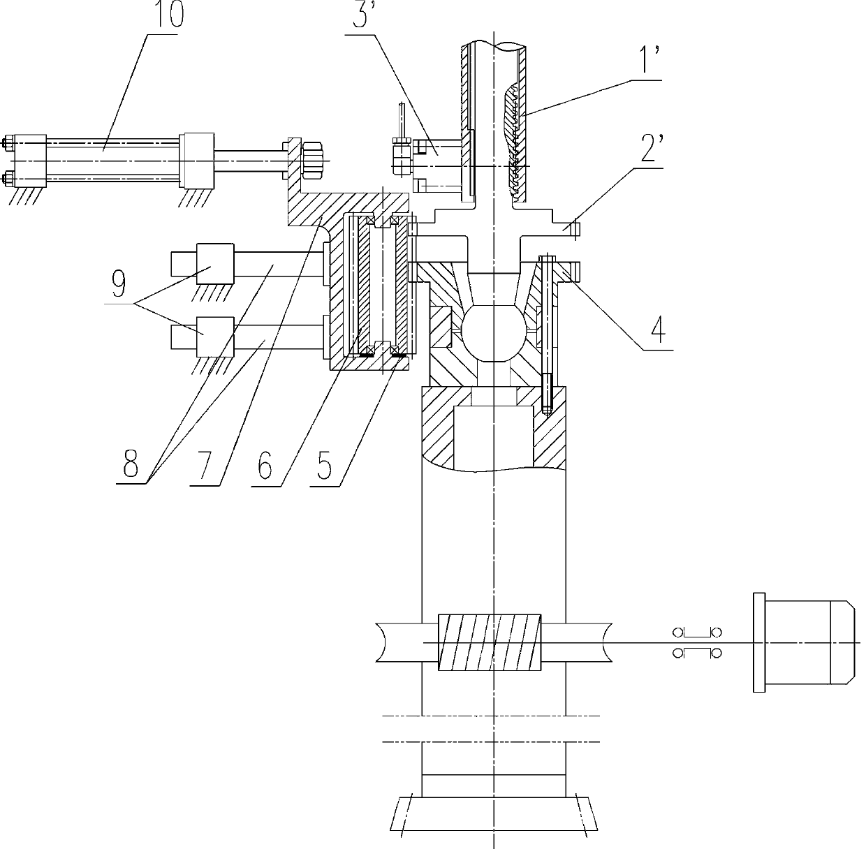
[0031] The method of adjusting the tool position by the automatic adjustment structure of the tool position of the gear shaper. When the tool position is adjusted, the swing rod stops to ensure that the ball tie rod 2' is in a vertical state, the thread locking cylinder 3' is filled with oil, and the locking is released. The thread of the ball tie rod; the oil cylinder 10 pushes the gear base 7, and pushes the transition gear 6 to move through the gear base 7, so that the transition gear 6 meshes with the first gear of the ball tie rod 2' and the second gear 4 on the gear cover at the same time; The tooth-splitting motor of the cutter drives the cutter shaft to rotate, the cutter shaft synchronously drives the second gear 4 to rotate, and then drives the transition gear 6 synchronously through the second gear 4, drives the ball tie rod 2' to rotate through the transition gear 6, and then passes the swing rod 1 ' and the thread on the ball tie rod 2' drive the ball tie rod 2' to...


PUM


Abstract

The invention provides an automatic adjustment structure and method of a cutter position of a gear shaper. The automatic adjusting structure of the cutter position of the gear shaper comprises a swingrod; a ball pull rod is installed inside the swing rod through a thread in a transmission fit mode; a first gear is machined on the ball pull rod; a second gear is machined on a ball pull rod gland matched with the ball pull rod; an oil cylinder is fixedly installed on a vertical column of a gear shaper body; a gear seat is fixedly installed at the tail end of a piston rod of the oil cylinder; transition gears are installed inside the gear seat; the transition gears are in meshing transmission with the first gear and the second gear at the same time; and the gear seat is matched with a guidemechanism fixed on the gear shaper body. According to the automatic adjustment structure of the cutter position of the gear shaper, a ball pull rod and a cutter shaft of a traditional gear shaper arerespectively provided with a gear, the other transition gear is pushed by the oil cylinder to be engaged with the two gears at the same time, then the cutter shaft is driven to rotate by a motor of the gear splitting movement of the cutter shaft and to drive the ball pull rod to rotate, the up-and-down movement of the cutter shaft is finally realized, and the automatic adjustment of the cutter position is realized.

Description

technical field [0001] The invention relates to the field of gear shapers, in particular to a structure and method for automatic adjustment of tool positions of a gear shaper. Background technique [0002] When the gear shaper is processing gears, due to the wear of the tip of the gear shaper, the tool needs to be sharpened after a certain number of workpieces are processed, and the thickness of the tool will gradually become thinner, so the position of the tool needs to be adjusted continuously. At the same time, due to the production of different workpieces or fixtures It will lead to the change of the tooth position of the workpiece, and the adjustment of the tool position is also required. At present, the adjustment method of the gear shaper tool position at home and abroad mostly adopts manual adjustment, such as figure 1 , this method has the following disadvantages: [0003] 1. The operation is inconvenient. It is necessary to manually loosen the locking screw (3) o...

Claims


Application Information

Patent Timeline
Patent Type & Authority Applications(China)
IPC IPC(8): B23F5/12B23F23/00
CPCB23F5/12B23F23/00
Inventor 王伟
Owner 宜昌长机科技有限责任公司
Why Eureka
Try Eureka