Check patentability & draft patents in minutes with Patsnap Eureka AI!

Feeding-discharging cantilever for laser cutting machine

A laser cutting machine and cantilever technology, applied in laser welding equipment, welding equipment, metal processing equipment, etc., can solve problems such as safety production accidents, reduce production efficiency, and affect production progress, so as to isolate potential safety hazards, improve production efficiency, The effect of high degree of automation

Pending Publication Date: 2019-11-05
江苏弘东工业自动化有限公司
View PDF0 Cites 0 Cited by
  • Summary
  • Abstract
  • Description
  • Claims
  • Application Information

AI Technical Summary

Problems solved by technology

[0003] At present, during the operation of the laser cutting machine, the raw materials are loaded manually, and the unloading method is manually unloaded after the cutting is completed and cooled. The manual handling greatly reduces the production efficiency, and there are Large potential safety hazards, may also cause a series of safety production accidents due to improper human operation
[0004] With the advancement of science and technology, some laser cutting machines have been equipped with electromechanical control of loading and unloading manipulators and other equipment to replace manual handling and loading and unloading. The transmission between the various components is not synchronized, resulting in the loading and unloading action not meeting the production rhythm, affecting the production progress, and may also lead to problems such as waste

Method used


Image

  • Feeding-discharging cantilever for laser cutting machine
  • Feeding-discharging cantilever for laser cutting machine
  • Feeding-discharging cantilever for laser cutting machine

Examples


Embodiment Construction

[0034] The present invention will be further described below in conjunction with the accompanying drawings and specific embodiments.

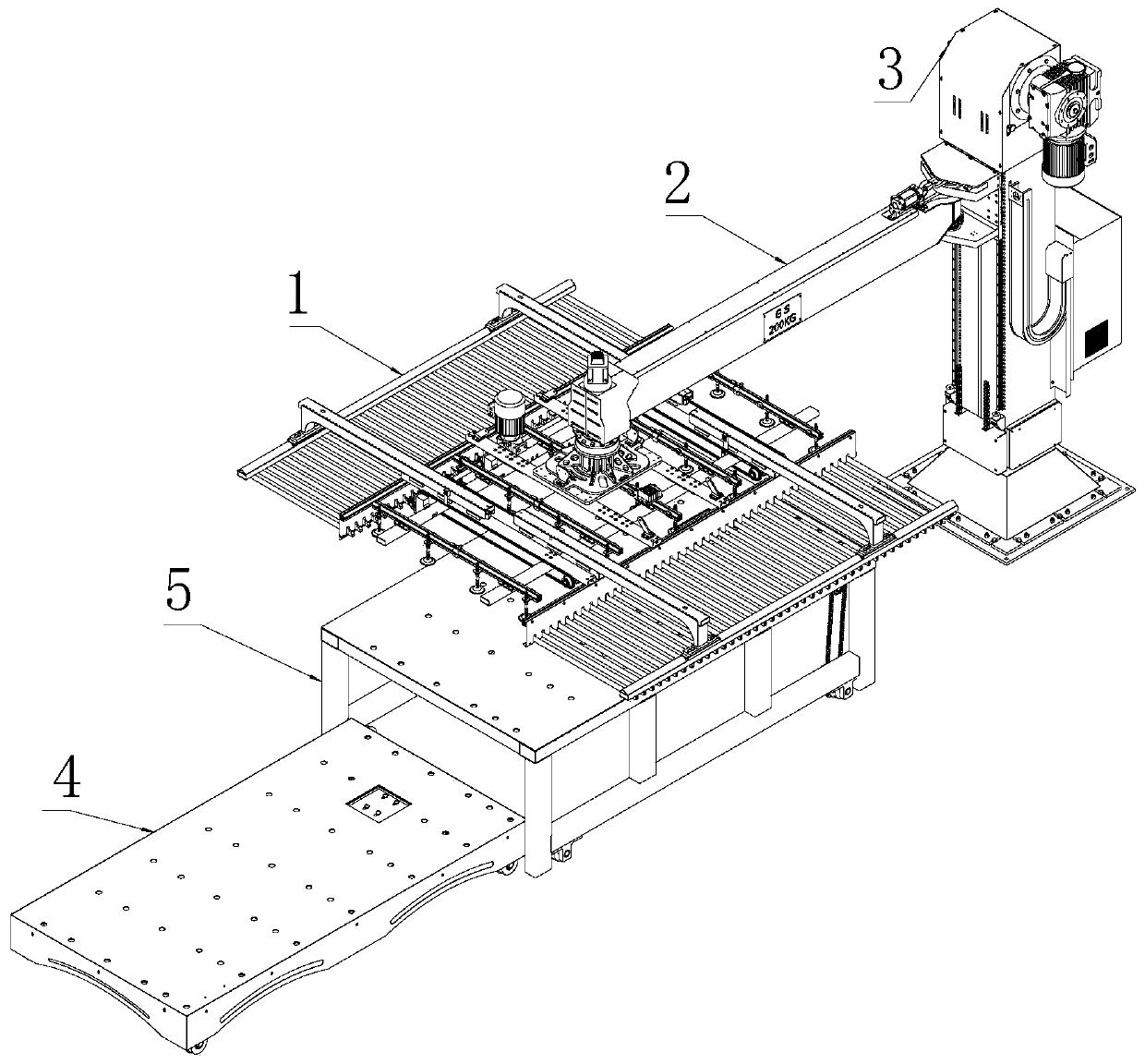
[0035] Please see attached figure 1 , a loading and unloading cantilever for a laser cutting machine, comprising a suction cup insert 1, a cantilever 2, a column 3, a raw material car 4 and a finished car 5.

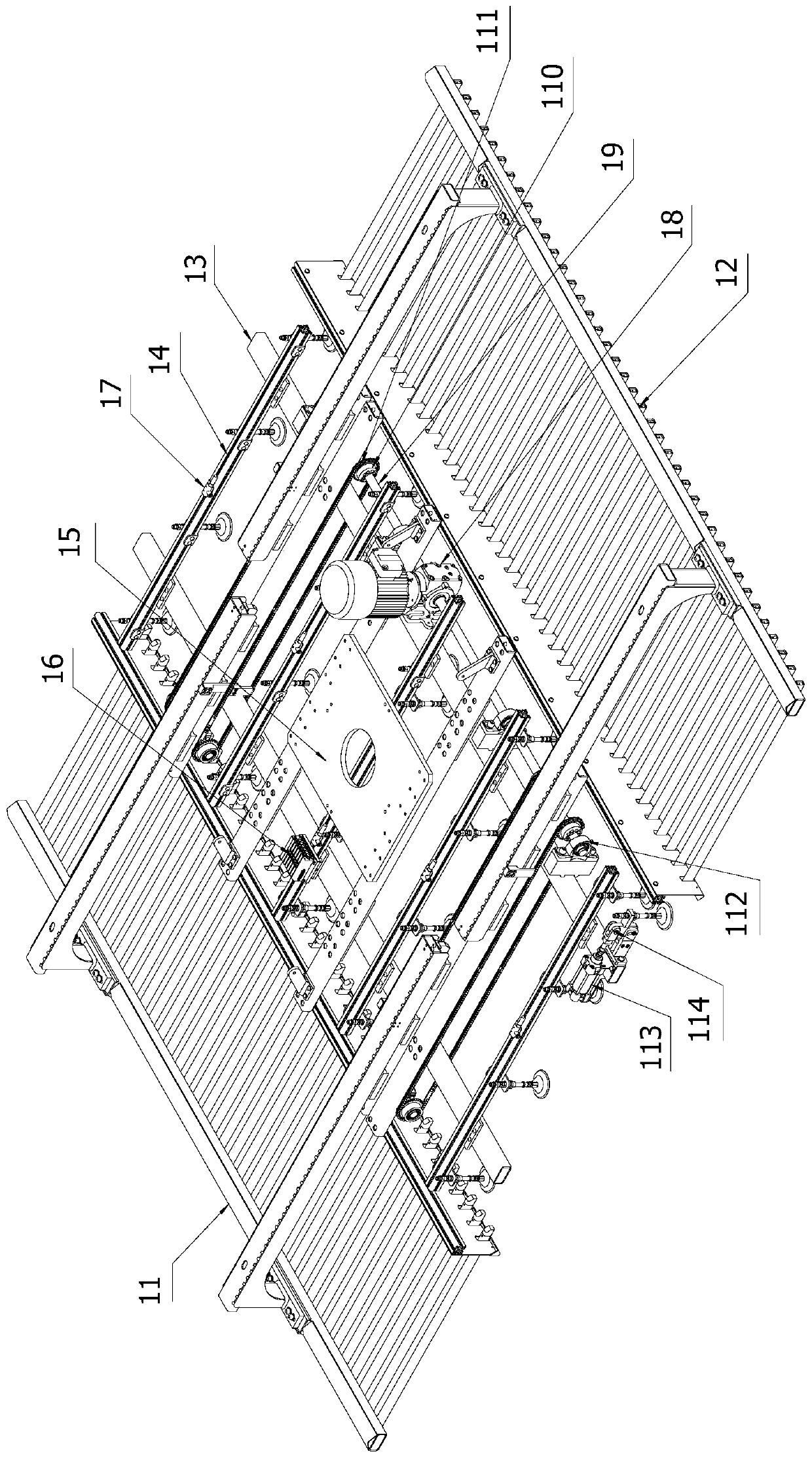
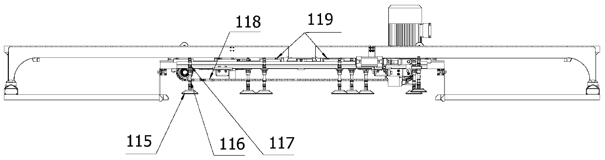
[0036] Please see attached figure 2 And attached image 3 , the suction cup socket 1 includes a suction cup socket main body 13, a suction cup mounting aluminum profile 14, a suction cup mounting motherboard 15, a pneumatic suction cup 115, a separation plate component, and a pneumatic control component; the suction cup mounting motherboard 15 is installed on the suction cup socket In the center of the frame main body 13, several suction cup mounting aluminum profiles 14 are arranged at intervals on the suction cup inserting frame main body 13, and several pneumatic suction cups 115 are installed at intervals on the bottom of each suct...


PUM


Abstract

The invention discloses a feeding-discharging cantilever for a laser cutting machine. The feeding-discharging cantilever comprises a suction cup inserting frame, a cantilever body, a vertical column,a raw material vehicle and a finished product vehicle; the suction cup inserting frame comprises a suction cup inserting frame main body, suction cup installing aluminum profiles, a suction cup inserting frame installing main board, pneumatic suction cups, a plate separating assembly and a pneumatic control assembly; the cantilever body comprises a cantilever main body, an up-down moving installation plate, a cantilever main body installation piece, a chain connection transition piece, an up-down moving guide slide block, a cantilever rotation main shaft, a cantilever up-down moving chain installation block, a servo driving assembly and a mechanical transmission assembly; the vertical column comprises a vertical column main body, a cabling drag chain, an up-down moving linear guide rail and an up-down transmission assembly; the raw material vehicle comprises a raw material vehicle main body and a raw material vehicle driving assembly; and the finished product vehicle comprises a finished product vehicle main body and a finished product vehicle driving assembly. According to the feeding-discharging cantilever, full-automatic feeding and discharging of the laser cutting machine are achieved through transmission of the electrical structure and the mechanical structure, accordingly, the production efficiency is greatly improved, and potential safety hazards are avoided.

Description

technical field [0001] The invention relates to a laser cutting machine, in particular to a loading and unloading cantilever used for the laser cutting machine. Background technique [0002] With the rapid development of the modern mechanical processing industry, the market has continuously improved the cutting quality and precision of sheet metal materials. Laser cutting machines are currently the cutting equipment with the fastest efficiency and the highest cutting precision, and are widely used in various cutting processes. . [0003] At present, during the operation of the laser cutting machine, the feeding method of the raw materials is manual handling and loading, and the unloading method is manual handling and unloading after the cutting is completed and cooled. The manual handling method greatly reduces the production efficiency, and there are Large potential safety hazards may also cause a series of safety production accidents due to improper human operation. [0...

Claims


Application Information

Patent Timeline
Patent Type & Authority Applications(China)
IPC IPC(8): B23K26/70B23K26/38
CPCB23K26/702B23K26/38Y02P70/10
Inventor 林忠吴达通曹宇许铮付红芝
Owner 江苏弘东工业自动化有限公司
Features
  • R&D
  • Intellectual Property
  • Life Sciences
  • Materials
  • Tech Scout
  • Unparalleled Data Quality
  • Higher Quality Content
  • 60% Fewer Hallucinations
Learn More