Three-pin-shaft fork sawing machine machining positioning clamp

A three-pin shaft fork and positioning fixture technology, applied in the field of auto parts processing, can solve problems such as unreasonable selection of clamping surfaces, influence of blank model size, and single type of processed parts, so as to improve labor productivity, and the clamping effect is obvious. The effect of ensuring machining accuracy

Pending Publication Date: 2019-11-05
上海伟奕传动轴配件有限公司
View PDF0 Cites 1 Cited by
  • Summary
  • Abstract
  • Description
  • Claims
  • Application Information

AI Technical Summary

Problems solved by technology

[0004] 1. The existing structure can only process two parts at the same time, and affected by the size of the blank, the type of processed parts is single and the processing efficiency is low
[0005] 2. The product parts are directly placed on the bottom plate of the fixture, relying on the outside of the part itself as a clamping support, and the selection of the clamping surface is unreasonable
[0006] 3. Relying on the bottom plane of the part as the processing reference, affected by the bottom plane of the blank, the positioning is unreasonable
[0007] 4. The cylinder pushes the compression device directly on the corner of the part, the compression position is not good, the force is uneven, and the phenomenon of jitter and offset will occur
It is easy to affect the measurement size, resulting in the scrapping of parts processing; and even the positioning deviation of the customer's subsequent processing, causing customers to complain about processing

Method used


Image

  • Three-pin-shaft fork sawing machine machining positioning clamp
  • Three-pin-shaft fork sawing machine machining positioning clamp
  • Three-pin-shaft fork sawing machine machining positioning clamp

Examples


Embodiment Construction

[0027] In order to make the object, technical solution and advantages of the present invention clearer, the present invention will be further described in detail below in combination with specific examples and with reference to the accompanying drawings. It should be understood that these descriptions are exemplary only, and are not intended to limit the scope of the present invention. Also, in the following description, descriptions of well-known structures and techniques are omitted to avoid unnecessarily obscuring the concept of the present invention.

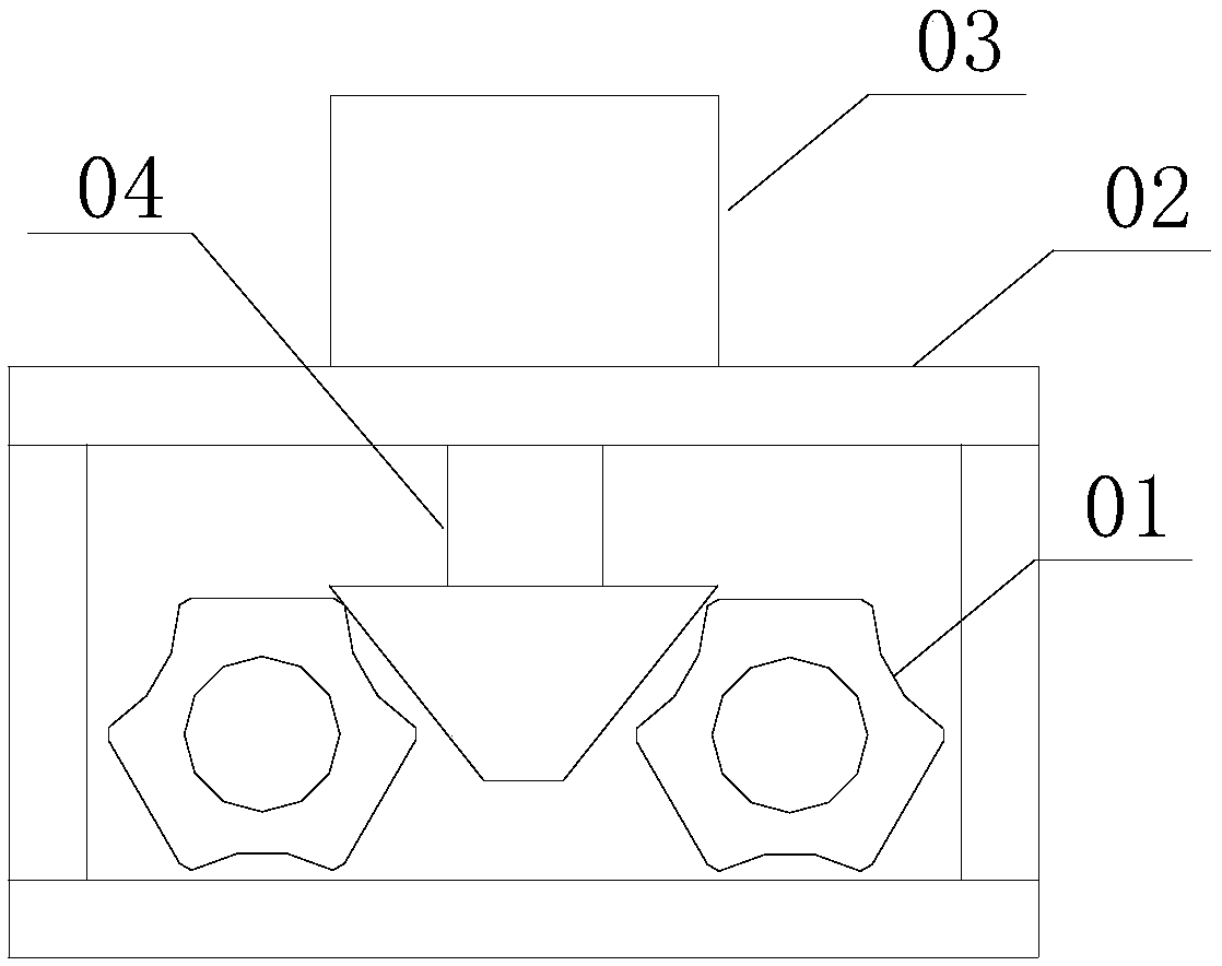
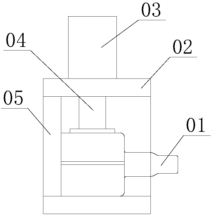
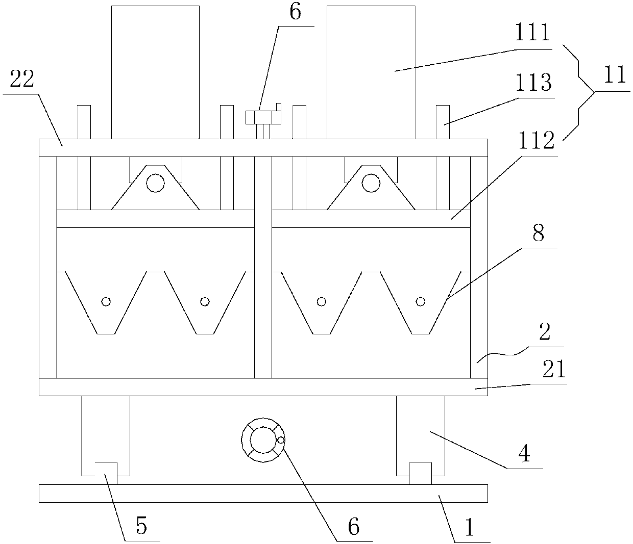
[0028] The invention relates to a processing and positioning fixture for a three-pin shaft fork sawing machine, which comprises a base 1 and a clamp body 2 arranged on the base 1 . Between the base 1 and the clamp body 2, there is a front and rear adjustment device 3 that can make the clamp body 2 move back and forth along the base. The front and rear adjustment device 3 is a screw drive adjustment device, and the lower part...


PUM


Abstract

The invention discloses a three-pin-shaft fork sawing machine machining positioning clamp which comprises a base and a clamp body arranged on the base. A front-back adjusting device capable of makingthe clamp body move front and back along the base is arranged between the base and the clamp body. A bottom plate is arranged at the lower portion of the clamp body, and positioning grooves which arein multiple stations and are used for fixing three-pin-shaft forks are formed in the lower portion of the interior of the clamp body side by side. Blank inner cavity positioning devices used for positioning inner cavities of the three-pin-shaft forks are correspondingly arranged at the positions, in the front-back direction of the clamp body, above the positioning grooves, wherein the number of the blank inner cavity positioning devices is the same with that of the positioning grooves. Vertical adjusting device capable of making the blank inner cavity positioning devices move vertically are arranged at the rear portions of the blank inner cavity positioning devices. Pressing devices are arranged above the blank inner cavity positioning devices, and the pressing devices include pressing aircylinders and pressing plates arranged at the power output ends of the pressing air cylinders. By means of the three-pin-shaft fork sawing machine machining positioning clamp, the structure is simple, positioning is stable and reasonable, the machining efficiency is high, the coverage of the machining specifications and sizes is wide, the measuring size is ensured, and scraping caused by inaccurate positioning of parts is effectively avoided.

Description

technical field [0001] The invention relates to the technical field of auto parts processing, in particular to a processing positioning fixture for a three-pin shaft fork sawing machine. Background technique [0002] When the existing auto parts are processed by the three-pin shaft fork sawing machine, the clamping device is as attached figure 1 As shown: firstly, the product part 01 is directly loaded into the vehicle fixture 02, and the part 01 touches the fixture and then the plate is positioned; then the cylinder 03 pushes the compression device 04 to compress the workpiece for processing. [0003] The above-mentioned clamping device has the following disadvantages: [0004] 1. The existing structure can only process two parts at the same time, and affected by the size of the blank, the type of processed parts is single and the processing efficiency is low. [0005] 2. The product parts are directly placed on the bottom plate of the fixture, relying on the outside of t...

Claims


Application Information

Patent Timeline
Patent Type & Authority Applications(China)
IPC IPC(8): B23Q3/06B23Q3/08
CPCB23Q3/061B23Q3/08
Inventor 张伟智
Owner 上海伟奕传动轴配件有限公司
Why Eureka
Try Eureka