Heavy load mechanical arm

A technology of manipulators and manipulators, applied in the field of manipulators, can solve the problems of casting weight, large size, large human injury, high labor cost, etc., and achieve the effect of stable movement, good effect and low cost

Pending Publication Date: 2019-11-05
NINGXIA KOCEL MOLD
View PDF9 Cites 2 Cited by
  • Summary
  • Abstract
  • Description
  • Claims
  • Application Information

AI Technical Summary

Problems solved by technology

Especially, in the traditional casting industry, due to the weight and size of the castings, it is difficult to carry them. At the same time, most of the castings are polished manually, which not only has low efficiency and high labor costs, but also causes great harm to the human body.
There are still many subsequent processes that require manipulators, but if the production line is equipped with various manipulators, the cost will be very high. Now it is necessary to propose a general-purpose heavy-duty manipulator suitable for production to reduce costs and improve post-processing of castings. efficiency and reduce labor intensity

Method used


Image

  • Heavy load mechanical arm
  • Heavy load mechanical arm
  • Heavy load mechanical arm

Examples


Embodiment 1

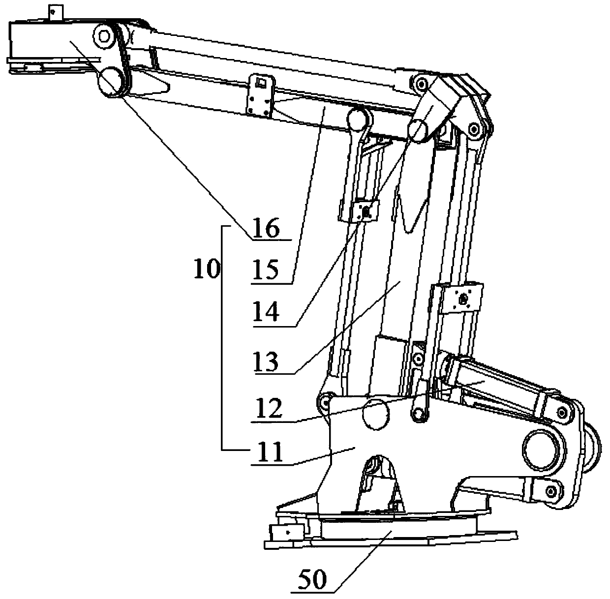
[0043] Refer to attached Figure 1-3 As shown, a heavy-duty manipulator includes a manipulator 10 , a connection device 20 , and an execution device. The manipulator 10 is connected to the execution device through the connection device 20 . The execution device is one of the grabbing device 30, the relief grinding device 40, the cutting device or the welding device, and then the heavy-duty manipulator can be set on the heavy-duty AGV, and then move in the workshop. One position, or multiple positions, and then realize the free switching of the executive parts of the robotic arm, and the free movement of the heavy-duty manipulator to cooperate and complete various tasks.

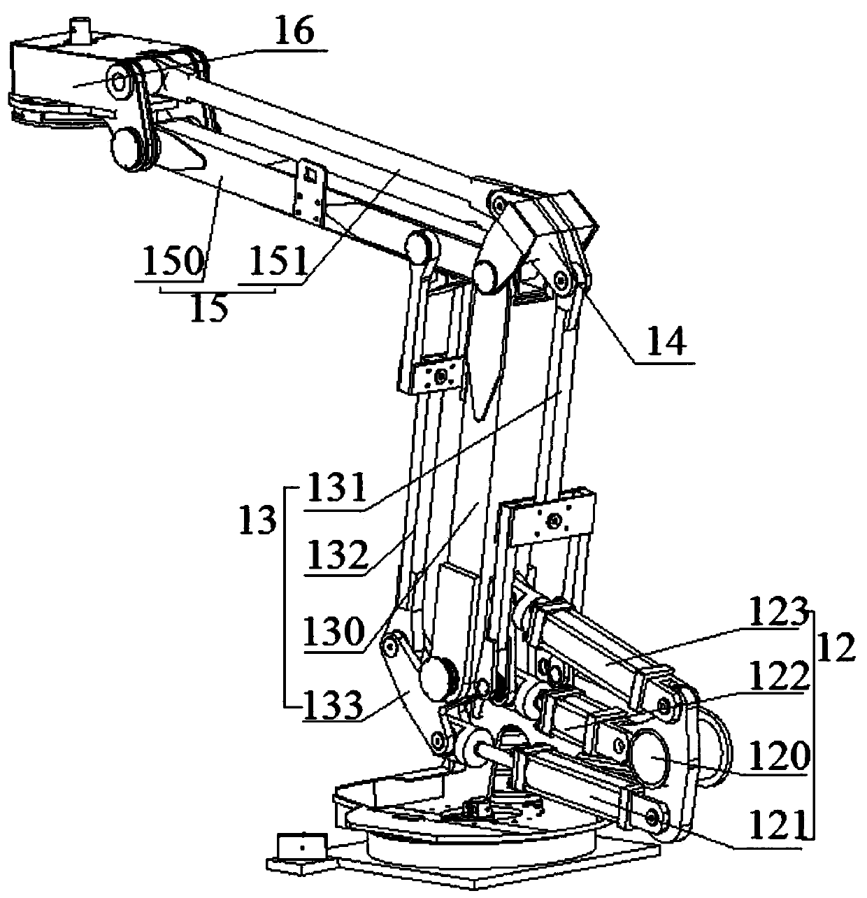
[0044] The mechanical arm 10 includes a fixed seat 11 , an oil cylinder group 12 , a vertical arm group 13 , a first T-shaped piece 14 , a horizontal arm 150 group 15 , and a connecting head 16 .

[0045] The cylinder group 12 includes a second T-shaped piece 120 , a vertical telescopic cylinder 121 , a bala...

Embodiment 2

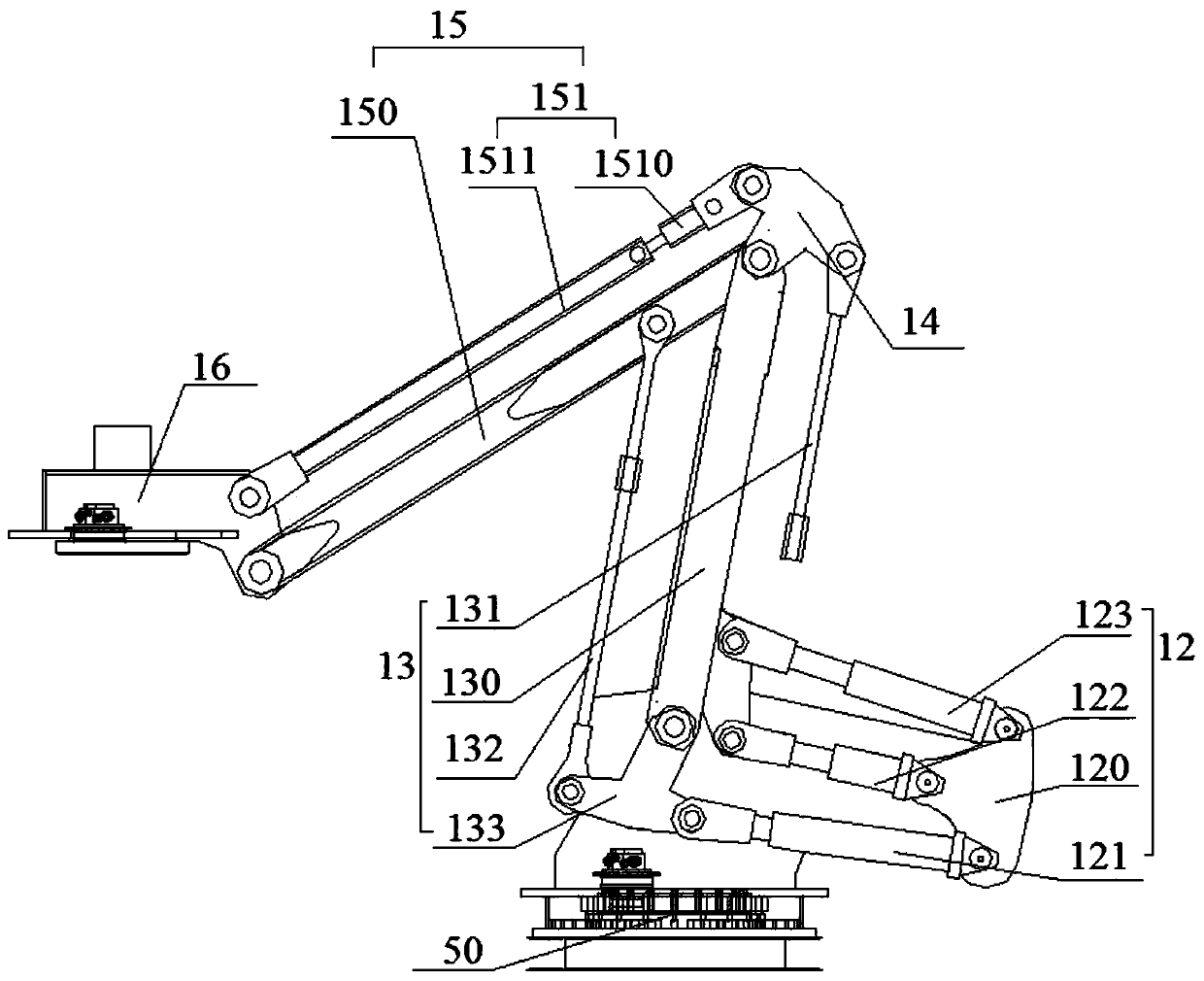
[0052] Refer to attached Figure 4 As shown, on the basis of Embodiment 1, the horizontal link 151 is divided into two parts, and a buffer 1510 is added. Specifically, the horizontal link 151 includes a buffer 1510 and a horizontal rod 1511. One end of the buffer 1510 is connected to the second A T-shaped piece 14 is hinged, and the other end is hinged with the horizontal rod 1511, and the other end of the horizontal rod 1511 is hinged with the connector 16; the buffer 1510 includes a sleeve A15101, a sleeve B15102, a piston rod 15103, spring 15104, adjusting collar 15105, the sleeve A15101 is cylindrical with one end open, the sleeve B15102 is cylindrical with one end open, and a piston rod 15103 is arranged in the middle, and the piston rod 15103 is fixedly connected with the closed end. The sleeve B15102 is tightly fitted on the outside of the sleeve A15101, and the free end of the piston rod 15103 is located in the sleeve A15101, and the outside of the closed end of the sl...

Embodiment 3

[0054] Refer to attached Figure 5-8 As shown, on the basis of Embodiment 1 or Embodiment 2, a rotary base 50 is included, and the rotary base 50 includes a fixed plate 31 and a rotary drive, and the fixed plate 31 is fixedly connected to the bottom of the fixed seat 11. The rotary drive drives the fixed disk 31 to rotate. The heavy-duty manipulator can complete the movement in all directions up, down, left, right, front and back.


PUM


Abstract

A heavy load mechanical arm comprises a mechanical arm, a connection device and an execution device, wherein the mechanical arm is connected with the execution device through the connection device. The heavy load mechanical arm achieves switching of multiple functions of grabbing, relief grinding, cutting, welding and the like through the same mechanism arm, is stable when using a three cylinder mechanical arm, is applicable to the heavy load field, and meets grabbing and relief grinding demands due to the structure of the mechanical arm, thereby achieving the purposes of saving cost and working stably and safely.

Description

technical field [0001] The invention relates to the field of manipulators, in particular to a heavy-duty manipulator. Background technique [0002] As the main key equipment in important manufacturing equipment, the mechanical arm has been widely studied and is mainly used in machinery, metallurgy, casting and other fields. It can replace people to carry out heavy and dangerous manual work to a certain extent. Especially, in the traditional casting industry, due to the weight and size of the castings, it is difficult to carry them. At the same time, most of the castings are polished manually, which not only has low efficiency and high labor costs, but also causes great harm to the human body. There are still many subsequent processes that require manipulators, but if the production line is equipped with various manipulators, the cost will be very high. Now it is necessary to propose a general-purpose heavy-duty manipulator suitable for production to reduce costs and improve...

Claims


Application Information

Patent Timeline
Patent Type & Authority Applications(China)
IPC IPC(8): B25J11/00B25J9/14B25J15/08
CPCB25J11/00B25J9/14B25J15/08
Inventor 朱强黄部东彭凡刘轶
Owner NINGXIA KOCEL MOLD
Why Eureka
Try Eureka