Porous pneumatic damper

An aerodynamic damper and aerodynamic damping technology, used in bridge parts, bridge construction, building components, etc., can solve the problems of high temperature heat dissipation, difficult to stabilize control, leakage, etc., to reduce construction cost and maintenance cost, achieve heat dissipation effect, avoid temperature The effect of rising too much

Pending Publication Date: 2019-11-05
EAST CHINA JIAOTONG UNIVERSITY
View PDF0 Cites 5 Cited by
  • Summary
  • Abstract
  • Description
  • Claims
  • Application Information

AI Technical Summary

Problems solved by technology

However, traditional liquid dampers rely on external media, such as silicone oil, magnetorheological fluid, etc., which have high-temperature heat dissipation and leakage problems, and are not easy to achieve stable control

Method used


Image

  • Porous pneumatic damper
  • Porous pneumatic damper
  • Porous pneumatic damper

Examples


Embodiment 1

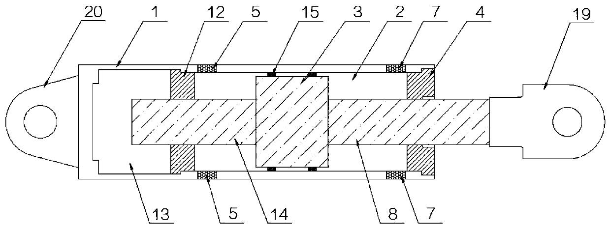
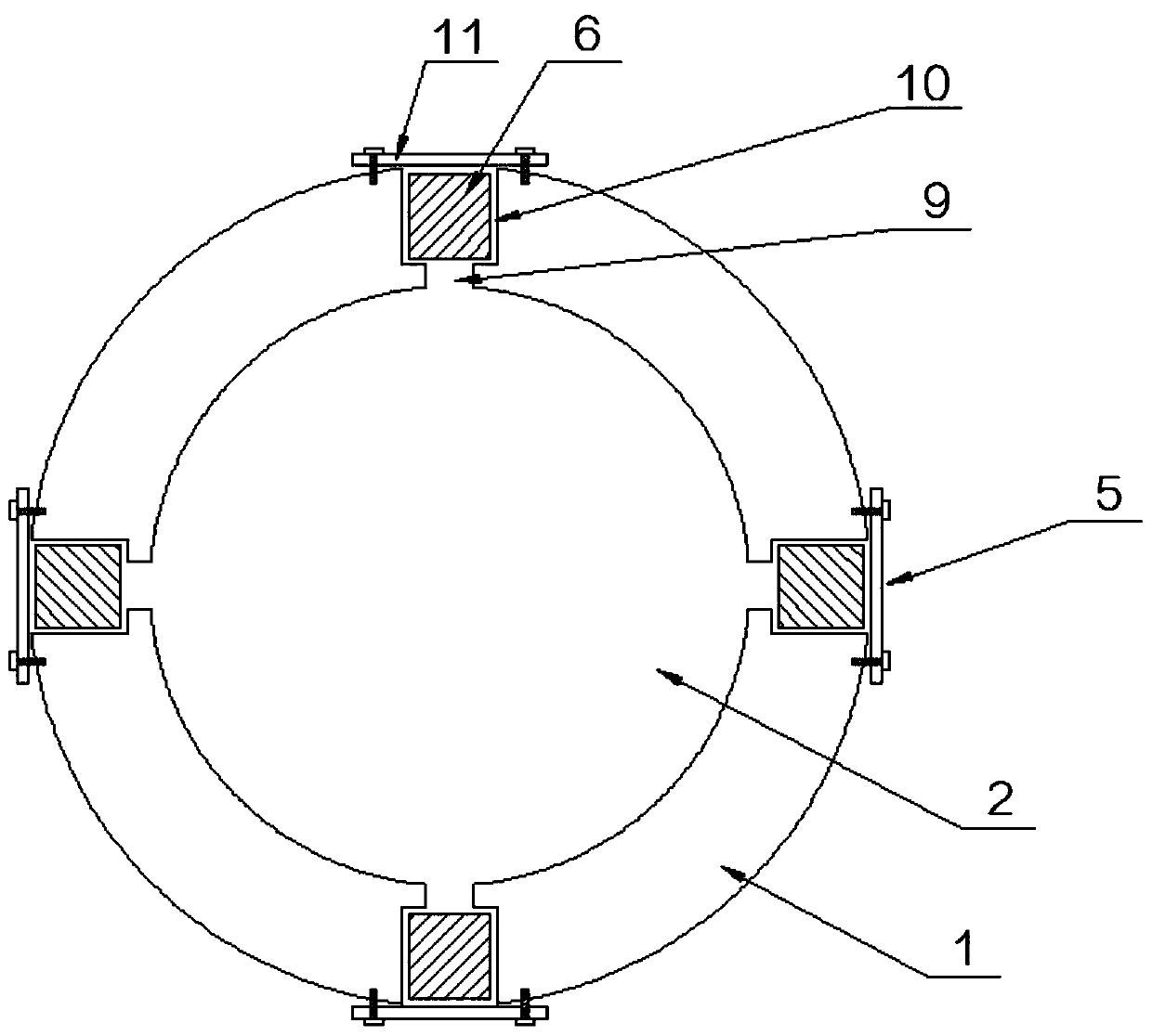
[0028] Such as Figure 1-3 As shown, a porous pneumatic damper includes an outer sleeve 1, a cavity 2 is opened in the outer sleeve 1, a piston 3 is arranged in the cavity 2, and one end of the outer sleeve 1 is opened A first sealing member 4 is fixedly arranged at the place;

[0029] One end of the outer sleeve 1 is provided with a first pneumatic damping hole 5, and the other end of the outer sleeve 1 is provided with a second pneumatic damping hole 7, and the first pneumatic damping hole 5 and the second pneumatic damping hole 7 Porous medium valve bodies 6 are respectively fixed inside, the piston 3 is located between the first pneumatic damping hole 5 and the second pneumatic damping hole 7, a first piston rod 8 is arranged on one side of the piston 3, and the The first piston rod 8 passes through the first sealing member 4 and passes out of the outer sleeve 1 .

[0030] One end of the outer sleeve 1 is provided with a plurality of first pneumatic damping holes 5 at in...

Embodiment 2

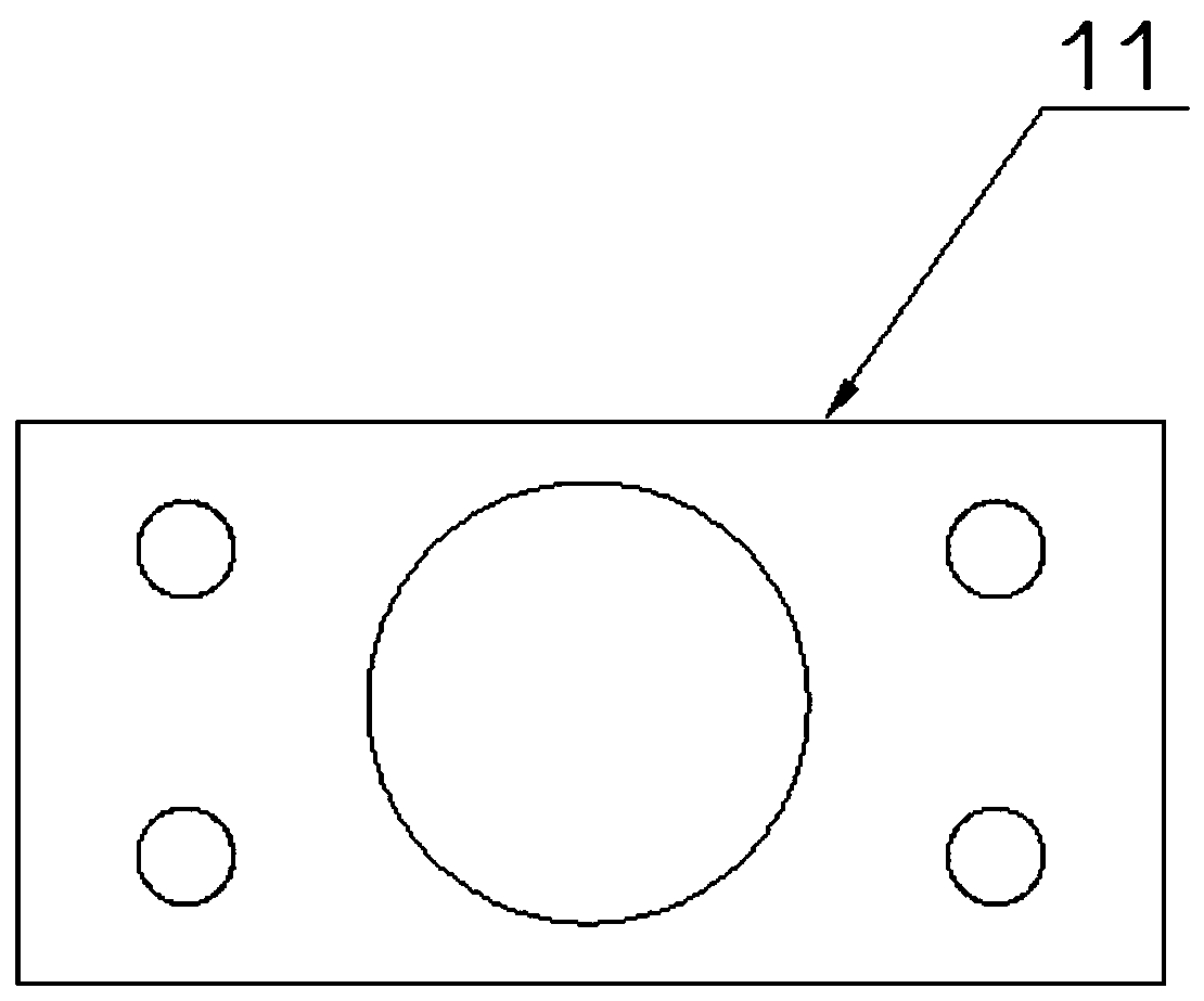
[0043] On the basis of Embodiment 1, the first pneumatic damping hole 5 and the second pneumatic damping hole 7 both include bolt installation grooves 16, and the bolt installation grooves 16 communicate with the cavity and the outside of the outer sleeve 1. The inner wall of the bolt mounting groove 16 is provided with an internal thread;

[0044]Also includes a bolt fastening mechanism 17, the bolt fastening mechanism 17 includes a bolt upper sleeve 171 and a bolt lower sleeve 172 that are mutually adapted, and the bolt upper sleeve 171 includes a head 1711 and a rod 1712 The head 1711 and the stem 1712 both include a second vent hole 1713, the second vent 1713 runs through the head 1711 and the stem 1712, and the outer wall of the stem 1712 of the bolt upper sleeve 171 is provided There are external threads, and a porous medium installation groove 10 is opened in the lower sleeve 172 of the bolt, and a third ventilation hole 18 is opened at the bottom of the porous medium i...


PUM


Abstract

The invention discloses a porous pneumatic damper. The porous pneumatic damper comprises an outer sleeve, wherein the outer sleeve is internally provided with a cavity; a piston is arranged in the cavity; a first sealing element is fixedly arranged at an opening formed in one end of the outer sleeve; first pneumatic damping holes are formed in one end of the outer sleeve; second pneumatic dampingholes are formed in the other end of the outer sleeve; porous medium valve bodies are respectively and fixedly arranged in the first pneumatic damping holes and the second pneumatic damping holes; thepiston is positioned between the first pneumatic damping holes and the second pneumatic damping holes; and a first piston rod is arranged on one side of the piston, penetrates through the first sealing element and penetrates out of the outer sleeve. According to the porous pneumatic damper disclosed by the invention, gases are always changed in the process that the gases enter or exit from the cavity, the heat dissipating effect can be realized on the premise of ensuring the damping effect, and excessive internal temperature rise of the damper is avoided; and a damping medium is natural gas and is independent of liquid media such as silicone oil, so that the problem of reduced damping force caused by excessive temperature rise is avoided.

Description

technical field [0001] The invention belongs to the technical field of shock absorbing dampers, and in particular relates to a porous pneumatic damper. Background technique [0002] The destruction of buildings, bridges and other structures due to earthquake or wind load excitation will cause casualties and direct or indirect serious economic losses. In seismic codes, reinforced structural members are usually used to consume the energy of earthquake or wind vibration by using the elastic-plastic deformation of the structure itself, so as to ensure the safety and normal use of buildings and bridge structures. In order to more effectively ensure the safety and normal use of structures such as buildings and bridges, structural vibration control technologies such as seismic isolation or energy dissipation and vibration reduction technologies have been introduced into the civil engineering field. [0003] As an intelligent shock-absorbing energy-consuming device, the main functi...

Claims


Application Information

Patent Timeline
Patent Type & Authority Applications(China)
IPC IPC(8): E04B1/98E04H9/02E01D19/00
CPCE01D19/00E04B1/98E04H9/02
Inventor 黄永虎张红丽郭鹏飞罗文俊万云
Owner EAST CHINA JIAOTONG UNIVERSITY
Why Eureka
Try Eureka